
Manufacturing Equipment & Production Lines
Our 100,000-square-meter workshop houses eight dedicated production lines, each engineered for a specific class of steel structure component — from CNC plasma cutting of 120mm plate to robotic saddle cutting of 400mm pipe. This page documents the equipment, its technical specifications, and the production logic that enables 200,000 tons of fabricated steel to leave our gates every year.
Eight Production Lines, Each Built for a Specific Engineering Problem
A steel structure factory is not a single production line — it is a sequence of specialized workstations, each calibrated for a specific material, geometry, and tolerance. When a project enters our workshop, it does not follow a generic path. Bolted-sphere grid nodes go to CNC sphere drilling. Pipe truss members go to CNC tube cutting and robotic saddle welding. H-beams go to the automated assembling and submerged-arc welding line. Box columns go to the multi-wire SAW station with electroslag welding for internal diaphragms.
This specialization matters because every component type has a different critical dimension. For a bolted-sphere grid node, the critical dimension is the bolt-hole angle on the sphere surface — a fraction of a degree off means the connecting member will not align. For a pipe truss, the critical dimension is the saddle-cut profile at the branch-to-chord intersection — an imprecise cut creates a root gap that no amount of welding can compensate for structurally. For an H-beam, the critical dimension is flange-to-web squareness after welding — angular distortion propagates into frame misalignment during erection.
Each of the eight production lines below is configured to control its critical dimension to engineering tolerance, not workshop approximation.
CNC Plasma & Oxy-Fuel Cutting Line
Multi-torch cutting with automatic nesting, bevel preparation, and plate thickness capacity from 6mm to 120mm.
Every steel structure component begins as a steel plate or section arriving from the mill. The CNC cutting line is where mill material becomes engineered components — and where dimensional accuracy is either established or lost before any welding begins. Our cutting line integrates CNC plasma and oxy-fuel cutting machines with automatic nesting software that reads design data directly from the CAD/CAM pipeline.
Multi-torch configuration. Each cutting machine carries up to four cutting torches operating simultaneously, each following an independent CNC path. This means four identical plate components can be cut from the same nesting layout in a single pass, or four different components can be cut in parallel from the same plate. The nesting software optimizes plate utilization by arranging component geometries to minimize skeleton waste, typically achieving 82–92% material utilization depending on component geometry complexity.
Plate thickness capacity: 6mm to 120mm. The thinner range (6–12mm) is cut by plasma for speed and minimal heat-affected zone. The thicker range (25–120mm) is cut by oxy-fuel for straight-edge quality on thick plate. For plate above 40mm, the cutting line supports multi-pass bevel cutting, where the torch is angled to cut V, X, or K bevels in a single setup — preparing the weld groove directly on the cutting machine, eliminating a separate beveling operation and the dimensional error it introduces.
Cutting tolerance. The CNC controller maintains cutting path accuracy to ±0.5mm on straight cuts and ±1.0mm on complex curves, including circular and elliptical cutouts. This tolerance is verified by post-cut dimensional scanning before the plate enters the welding line.
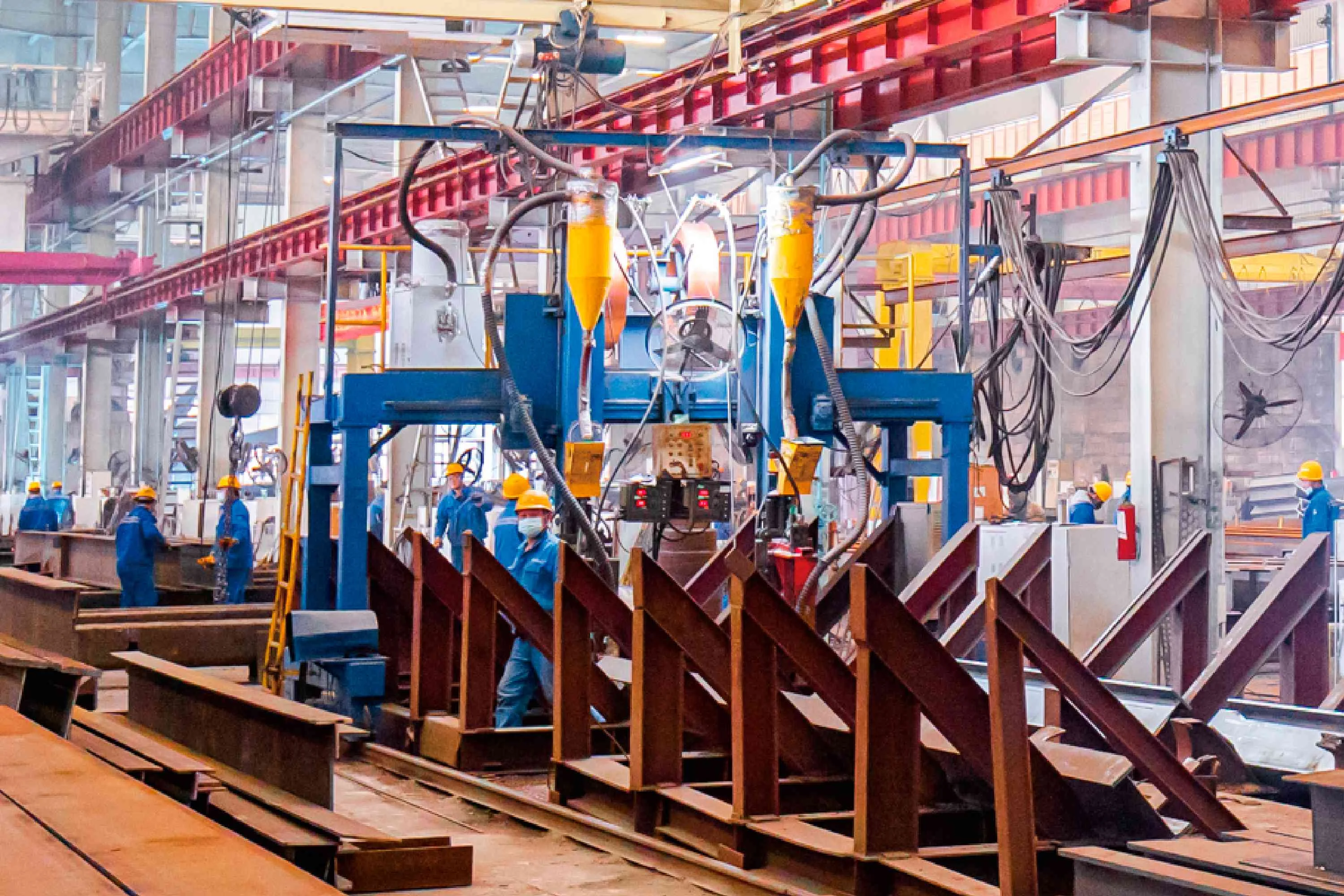
H-Beam Automated Welding Line
Gantry assembling, simultaneous twin-torch SAW welding, and hydraulic straightening in one continuous line.
H-beams are the backbone of industrial workshop frames, portal frames, and platform structures. Our H-beam welding line is a three-station continuous production line: assembling, welding, and straightening, each station fed by roller conveyors that maintain member alignment between operations.
Station 1 — Gantry Assembling. The flange and web plates are positioned by a gantry assembling machine that clamps the web between two flanges and tack-welds the T-joints at programmed intervals. Web-to-flange positioning is controlled by hydraulic centering to ±1.0mm, preventing the offset that would propagate into angular distortion during welding. The assembling machine handles beam depths from 200mm to 1,500mm and flange widths up to 600mm.
Station 2 — Submerged-Arc Welding (SAW). The assembled H-beam enters a gantry-mounted twin-torch SAW station that welds both flange-to-web junctions simultaneously. Twin-torch welding balances heat input on both sides of the web, canceling angular distortion that single-side welding would produce. Welding parameters — current (300–600A), voltage (28–38V), and travel speed (25–50 cm/min) — are pre-set per steel grade and plate thickness, with flux delivery and recovery handled automatically. The result is a uniform full-penetration weld with controlled heat input that keeps distortion below L/1000 (where L is the beam length).
Station 3 — Hydraulic Straightening. Any residual angular distortion from welding is corrected by a hydraulic straightening machine that applies controlled pressure to the flange tips, bringing the beam back to flatness tolerance. Straightness is verified by a laser straight-edge before the beam advances to the surface treatment line.
Box Column Welding Station
Multi-wire SAW for main seams and electroslag welding for internal diaphragm plates. Maximum section: 1200 × 1200mm.
Box columns carry the axial loads of super-tall buildings, long-span bridge piers, and heavy industrial structures. Unlike H-beams, box columns are closed sections with internal diaphragm plates — transverse stiffeners welded inside the column at each floor level or load-transfer point. The challenge: the internal diaphragm welds are physically inaccessible to conventional welding equipment because the column walls enclose them.
Multi-wire SAW for longitudinal seams. The four longitudinal corner seams of the box column are welded by multi-wire submerged-arc welding, where two or three welding wires feed into a single weld pool simultaneously. Multi-wire SAW increases deposition rate by 50–80% over single-wire, reducing heat-affected zone width and total heat input per unit length. The maximum box section is 1200 × 1200mm, with wall thicknesses from 8mm to 60mm. Maximum column length is 15 meters per section, with field splicing for taller columns.
Electroslag welding for internal diaphragms. Internal diaphragm plates are welded to the column walls using through-thickness electroslag welding (ESW). ESW deposits weld metal through the gap between the diaphragm edge and the column wall, filling the joint from bottom to top in a single pass. The process requires an access slot cut into the column wall (typically 25–35mm wide), which is plug-welded closed after the ESW pass. This technique achieves full-penetration welds on joints that no manual welder or conventional welding arm can reach — the engineering requirement for box columns carrying 5,000+ tons of axial load.
Pre-heat and interpass temperature control. For high-strength steel (Q355, Q390, Q420, Q460), pre-heat temperature (80–150°C depending on grade and thickness) and interpass temperature (200–230°C) are monitored by contact pyrometers at each weld pass, with temperature data logged against the column's QR code for traceability.
Spatial Grid Node Manufacturing
CNC sphere drilling for bolted-sphere grid nodes. Bolt-hole angular accuracy: ±0.05 degrees.
Bolted-sphere grid structures are assembled from three component types: steel pipes (members), bolted spheres (nodes), and high-strength bolts. The sphere is the intersection point of up to nine members, each approaching at a different three-dimensional angle. If the bolt-hole angle on the sphere is off by even a fraction of a degree, the connecting pipe will not align — and in a spatial grid, one misaligned node propagates stress redistribution across the entire structure.
CNC sphere drilling. Our CNC sphere drilling center clamps the raw forged sphere (diameter range: 100–300mm) on a multi-axis rotary table that positions the sphere at any compound angle required by the design geometry. The drilling spindle machines each bolt hole to the specified angle, with angular accuracy of ±0.05 degrees and positional accuracy of ±0.15mm. The CNC controller reads node coordinates directly from the spatial grid design model, where each sphere's hole pattern is unique to its position in the grid.
Bolt-hole precision and tap quality. Bolt holes are drilled and tapped in a single setup. Thread quality is verified by go/no-go gauges, and thread depth is controlled to ensure full bolt engagement under the design tensile load. The sphere surface is marked with its node identification number, matching the BIM model, so that each sphere arrives at the correct grid intersection during site assembly.

Pipe Truss Manufacturing
CNC tube cutting with saddle-cut profiling. Pipe diameter range: 60–400mm. Robot-assisted branch welding.
Pipe trusses are used in long-span roofs, stadium canopies, airport terminals, and bridge structures where the visual quality of exposed tubular members matters as much as their structural performance. The branch-to-chord intersection in a pipe truss — the "saddle" joint — is the most geometrically complex cut in steel structure fabrication. An imprecise saddle cut creates a root gap between branch and chord, and welding over a root gap produces a joint that is visually obvious and structurally inferior.
CNC tube cutting. Our CNC tube cutting machine rotates the pipe on its longitudinal axis while a plasma or oxy-fuel torch traces the saddle-cut profile in the pipe wall. The CNC controller reads the intersection geometry — branch diameter, chord diameter, intersection angle, and bevel angle — directly from the design model and computes the cutting path. Pipe diameter range is 60–400mm, with wall thickness from 4mm to 25mm. The saddle-cut profile includes the weld bevel, so the cut pipe arrives at the welding station ready for assembly with no secondary beveling or grinding.
Robot-assisted saddle welding. After the branch pipe is positioned on the chord, a six-axis welding robot traces the saddle joint profile, executing a multi-pass weld with parameter control for root, fill, and cap passes. The robot's advantage over manual welding is consistency: the saddle joint is a three-dimensional curve, and manual welding produces variable leg length, penetration, and surface profile along the curve. The robot welds the entire joint to the same parameter set, producing a uniform fillet weld that meets both structural and visual requirements for exposed pipe trusses.
Shot Blasting & Surface Treatment
Sa 2.5 near-white metal blast cleanliness. Surface profile Rz 50–85µm for optimal coating adhesion.
Before any primer or paint is applied, every steel surface must be blast-cleaned to remove mill scale, rust, and surface contamination. The quality of surface preparation determines the service life of the anti-corrosion system — a paint system applied to inadequately prepared steel will delaminate within years, regardless of paint quality.
Automated shot blasting. Members pass through a roller-conveyor shot blasting machine where steel shot (S330 grade, 0.8–1.2mm diameter) is propelled at high velocity onto all surfaces of the member. The blasting parameters — shot flow rate, conveyor speed, and blast wheel power — are set to achieve Sa 2.5 cleanliness (ISO 8501-1, near-white metal), the standard required for high-performance anti-corrosion systems. This cleanliness level removes 95%+ of visible contamination, leaving a clean metallic substrate.
Surface profile (roughness). The blasting process creates a surface profile (anchor pattern) that gives the coating mechanical adhesion. We control the surface profile to Rz 50–85µm (measured by replica tape or surface profile gauge), the range specified by SSPC-PA 15 and most coating manufacturers' data sheets for epoxy and polyurethane systems. Too smooth (below Rz 50µm) and adhesion is insufficient; too rough (above Rz 85µm) and the peaks may protrude through the primer at the specified dry film thickness, creating pinpoint rust.
Environmental control. The blasting bay is climate-controlled to maintain relative humidity below 50% and substrate temperature above the dew point by at least 3°C, preventing flash rusting between blasting and priming. The time between blasting and primer application is kept under 4 hours to prevent re-oxidation of the freshly blasted surface.
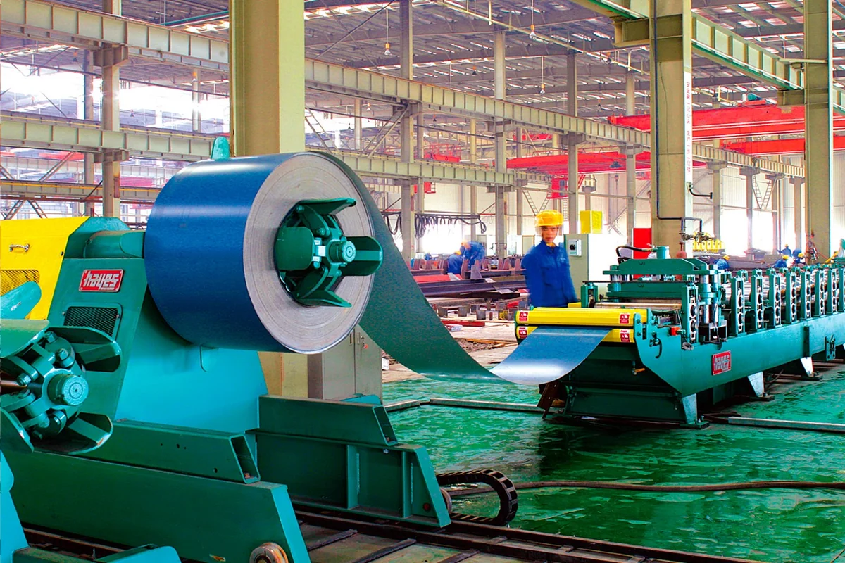
Spray Painting Line
Three-layer system: zinc-rich primer, epoxy intermediate, and polyurethane topcoat. Climate-controlled spray booths.
The spray painting line applies the anti-corrosion coating system to blasted members. The standard system for atmospheric-exposure steel structures is a three-layer paint system, but the specific products and dry film thicknesses are configured per project specification, environment class (C1 through C5-M per ISO 12944), and client requirements.
Layer 1 — Zinc-rich primer. A zinc-rich epoxy primer is applied as the first coat, providing both barrier protection and cathodic protection (galvanic sacrifice) at any point where the coating is damaged. The zinc content is typically 70–80% by weight in the dry film, and the dry film thickness is 50–75µm. Zinc-rich primer is the critical layer for long-term corrosion resistance — it is what prevents rust creep from coating damage sites.
Layer 2 — Epoxy intermediate coat. A high-build epoxy intermediate coat is applied over the primer, adding barrier thickness and creating a smooth surface for the topcoat. Dry film thickness is 80–125µm. The epoxy intermediate provides the majority of the system's total barrier thickness and is resistant to water, salt, and chemical exposure.
Layer 3 — Polyurethane topcoat. The topcoat is a polyurethane finish that provides UV resistance (preventing the epoxy underneath from chalking), color retention, and the final aesthetic finish. Dry film thickness is 40–60µm. For projects in C5-M environments (marine, offshore, extreme industrial), the topcoat is upgraded to fluorocarbon (FEVE) for extended UV and chemical resistance, as was specified for the Antarctica Ross Sea Station.
Dry film thickness (DFT) verification. After each coat and after the full system, DFT is measured by electronic gauge at multiple points per member (typically 5 readings per square meter). Readings are logged against the member's QR code, creating a per-member coating record that can be submitted to the client or inspector. Total system DFT for standard atmospheric exposure is 170–260µm; for C5-M marine environments, 240–320µm.
Inspection & Testing
Ultrasonic testing, magnetic particle testing, and CMM dimensional verification on every structural member.
The inspection and testing line is not a single workstation but a set of quality control processes embedded across the entire production flow. Inspection happens at every stage: incoming material verification, post-cut dimensional checks, in-process weld monitoring, post-weld NDT, and pre-shipping dimensional and visual verification.
Ultrasonic Testing (UT). Full-penetration welds on primary structural members are tested by ultrasonic testing, which detects internal defects (slag inclusion, lack of fusion, porosity, cracks) by reflecting high-frequency sound waves off discontinuities in the weld cross-section. UT is performed by certified Level II and Level III technicians per ISO 9712 or ASNT SNT-TC-1A. Acceptance criteria follow the applicable design standard (GB 50621, AWS D1.1, or EN 12062). UT pass rate on our production is 99.5%+ on first inspection; rejected welds are gouged, re-welded, and re-tested.
Magnetic Particle Testing (MT). Surface and near-surface cracks are detected by magnetic particle testing, where a magnetic field is applied to the ferromagnetic steel and fine iron particles reveal cracks at the flux leakage points. MT is applied to weld toes, branch connections, and high-stress zones where surface cracks are most likely to initiate under cyclic loading.
Dimensional CMM verification. Complex geometries — spatial grid nodes, pipe truss saddles, curved members — are verified by coordinate measuring machine (CMM) or 3D laser scan. The scan produces a point cloud of the fabricated member, which is overlaid on the BIM design model to verify dimensional compliance. Tolerance deviations are flagged, and members outside tolerance are reworked before they advance to the coating line or shipping. This is the final verification that what was designed is what was built — to the millimeter, not to the approximation.
Production Line Capabilities at a Glance
| Production Line | Key Capability | Capacity / Range | Tolerance |
|---|---|---|---|
| CNC Cutting | Plasma & oxy-fuel, multi-torch, bevel cutting | Plate: 6–120mm | ±0.5mm straight |
| H-Beam Welding | Twin-torch SAW, hydraulic straightening | Depth: 200–1500mm | Distortion < L/1000 |
| Box Column Welding | Multi-wire SAW, electroslag diaphragm welding | Section: up to 1200×1200mm | Full-penetration per code |
| Grid Node Drilling | CNC multi-axis sphere drilling | Sphere: Ø100–300mm | ±0.05° angular |
| Pipe Truss Cutting | CNC saddle cutting, robot welding | Pipe: Ø60–400mm | ±0.5mm profile |
| Shot Blasting | Automated wheel blasting | Sa 2.5, Rz 50–85µm | ISO 8501-1 Sa 2.5 |
| Spray Painting | 3-layer system, DFT logging | DFT: 170–320µm | Per ISO 12944 |
| Inspection & NDT | UT, MT, CMM / 3D laser scan | 100% primary welds | 99.5%+ UT pass rate |
Need a Steel Structure Built to Engineering Tolerance?
Send us your drawings or project requirements. Our engineering team reviews material grades, span, and load conditions, then confirms whether our production lines can meet your specifications — within 24 hours.
Contact Our Engineering Team