
High-Rise Steel Structure Systems: Drift Control, Wind Comfort and BRB Design
Above about 20 storeys, the design of a building stops being about strength and becomes about lateral stiffness: deflections, accelerations and second-order effects take over from member stresses, and the choice of structural system sets the whole economic envelope of the project. Steel earns its place in this range through three properties no other material matches together: strength-to-weight ratio that cuts foundation loads, shop-and-field speed that shortens the critical path by months, and ductility that lets a structure survive the design earthquake with controlled damage rather than collapse.
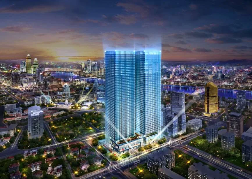
This guide is written for developers, architects, engineers and general contractors deciding which high-rise system to adopt and how to review the numbers in the structural report. It follows JGJ 99-2015 (Technical Specification for Steel Structure of Tall Buildings), GB 50011-2010 (Code for Seismic Design of Buildings), and cross-references AISC 360-16 where projects follow North American practice. The reference cases include the twin 265 m towers of Tianjin R&F Guangdong Tower, for which our workshops supplied structural steel, so the drift, comfort and brace numbers below are ones we have fabricated against, not only computed.
The article covers the system families and their heights, the two governing checks (inter-storey drift and occupant comfort), the P-Δ second-order reality, buckling-restrained braces, and the fire and floor systems that complete the steel tall building.
1. Structural Systems and Their Height Envelopes
Every tall building lateral system is a compromise between stiffness, cost and architectural freedom, and each has a height band where it is clearly the right answer. GB 50011-2010 Table 6.1.1 gives maximum applicable heights for steel buildings by seismic intensity; the practical bands below sit comfortably within it and reflect where each system is also economical.
| System | Typical height band | Lateral load resistance | Typical application |
|---|---|---|---|
| Steel moment frame | Up to 60 – 110 m | Beam–column rigid joints | Low-rise towers, flexible planning |
| Frame with braces (CBF / EBF / BRB) | 60 – 180 m | Vertical trusses in cores | Offices, hotels, residential towers |
| Frame–core (concrete core + steel frame) | 120 – 300 m | RC core + perimeter frame | Mixed-use super-talls, fastest construction |
| Mega frame (truss belts, mega columns) | 300 m and above | Outriggers, belt trusses, mega braces | Supertall towers (400+ m typical range) |
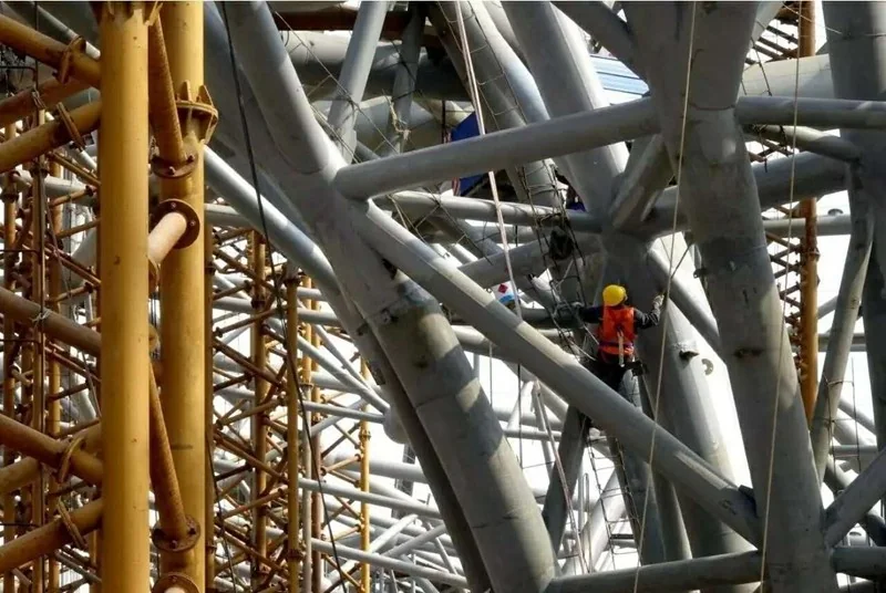
Within each band the system choice is refined by two further decisions: where the vertical lateral elements sit (core, perimeter or both), and how much of the shear is taken by braces instead of frame bending. The frame–core hybrid deserves particular attention because it is the default for 150–300 m mixed-use towers in China: a reinforced-concrete core provides the shear stiffness, the steel perimeter frame provides redundancy and speed, and the two are tied by outrigger and belt trusses at two to four levels. The Tianjin R&F towers sit in this family, and their steel package demonstrates the fabrication reality: heavy box columns, outrigger trusses with high-strength bolts, and composite floor systems repeated over dozens of storeys.
Steel Tonnage Benchmarks and Member Reality
Whole-building steel tonnage for central-China high-rises typically lands at 90–140 kg/m² of gross floor area for a 30–60 storey steel frame–core project in a low seismic zone, rising to 140–200 kg/m² where seismic intensity is high or the height-to-width ratio exceeds 6. The lateral system consumes 40–60% of that weight, which is why the system choice in this section, the drift budget in Section 2 and the brace strategy in Section 5 dominate the budget — gravity members are priced by architecture, lateral members by engineering judgment. Member reality follows: columns below about 600 mm are rolled H-sections, above that they are built-up box or heavy welded sections requiring full-penetration splices with UT at every shop splice and site splice — the fabrication detail that pushes weld inspection hours, and the reason the tonnage figure and the weld NDT budget are set by the same design decision.
2. Inter-Storey Drift Control: the H/400 Check
Inter-storey drift — the horizontal displacement of one storey relative to the one below, divided by the storey height — is the true sizing criterion of every tall building. JGJ 99-2015 sets the wind-serviceability limit at storey height / 400 (the H/400 check), protecting cladding, partitions, elevator rails and facade seals from distress. Under frequent earthquakes, the elastic drift limit for steel structures is storey height / 300 per GB 50011-2010, and under the rare design earthquake the elastoplastic drift may reach height / 50 before collapse of the collapse-resisting system is deemed acceptable.
For owners the practical translation is: a 60-storey tower (about 220 m) allowed height / 400 = 0.25% drift has a top displacement budget of roughly 550 mm — and the structural report should show which mechanism consumes it. Drift allocation matters: the core or braced bays take the shear-dominated story drift, while the frame provides the redundant moment path. When a design is "close but drifting too much," the fastest correction is not bigger beams; it is moving braces, adding outriggers or increasing core density — levers that add stiffness at a fraction of the weight cost.
Turning the Drift Number into Design Action
The H/400 wind limit and the H/300 frequent-earthquake limit look like simple ratios, but their application decides the entire lateral budget. At the design stage, the engineer allocates the drift budget between the translational movement of the frame and the shear distortion of the core or brace system, then checks each subsystem's contribution against its share. The practical consequence for the owner is that the drift report should show, for every storey, not just the total ratio but the split: core shear, brace deformation and frame sway. A report that shows only the total has not yet identified where the money should be spent to fix a failed check.
3. P-Δ Effects and System Stability
Every tall building carries its gravity load on a lateral system that is already swaying: the vertical load P acts through the horizontal displacement Δ, producing a second-order moment that a first-order analysis never sees. The stability coefficient θ = P·Δ / (V·h) condenses that amplification into one number per storey — storey gravity load times storey drift, divided by storey shear and storey height — and codes turn it into a three-step switch that a structural report should print at every level.
Stability coefficient θ = P·Δ / (V·h): θ ≤ 0.1 ignore; 0.1 < θ ≤ 0.25 amplify by 1/(1−θ); θ > 0.25 stiffen the structure
The amplification factor 1/(1−θ) in the middle band is the AISC 360-16 B2 expression and the equivalent in JGJ 99-2015: a design at θ = 0.2 carries a 25% moment tax on every beam and column from second-order effects, which is why the efficient tall building operates at θ below 0.15 wherever the plan allows the core or braces to be moved outward.
Chinese practice under JGJ 99-2015 accepts either a direct second-order analysis or a first-order analysis with the amplification factor applied member by member, provided the amplified demand is what reaches the member checks. A genuine second-order analysis must include the P-δ member effect (the bow of a member in its own chord) as well as the P-Δ storey effect, which is why the software default claiming “second-order effects included” deserves a hand-check against a computed θ on two or three typical storeys before it is trusted for the whole tower. The same verification catches modelling errors early: a θ profile that jumps discontinuously between consecutive storeys almost always reflects a break in the load path — a brace bay that vanished in one direction, or a core wall that changed depth — and that sensitivity is precisely what an owner needs at the scheme comparison stage, where one braced bay added to the weak direction can be worth several hundred tonnes of column steel.
What a Second-Order Review Report Must Show
- The θ coefficient for every storey, in both horizontal directions, against the 0.1 / 0.25 code thresholds.
- The amplification factor actually applied to member moments, or explicit second-order results with drift reported after amplification.
- Confirmation that P-δ (member bowing) is included in any software claim of “second-order analysis”.
- A re-run of the check after any major system change — new outrigger, relocated brace bay, changed core — since θ depends on the final stiffness distribution.
One subtlety separates a stability review from a paperwork exercise: the P-Δ check must be run in both orthogonal directions, including the direction where the structure is only 60% as stiff, because the governing second-order response is almost always in the weak direction. It must also be re-run after every major system change (adding an outrigger, moving a brace bay), since the stability coefficient is a property of the final stiffness distribution, not of the initial scheme. Where the storey drift is supplied by the analysis software directly, the engineer should verify that the reported drift already includes the second-order amplification requested by the code — a non-amplified drift number compared against an amplified limit is one of the most common review findings on exported tall-building reports.
4. Wind-Induced Vibration and Occupant Comfort
A tall building can pass every strength and drift check and still fail its users: at 150 m and above, wind-induced acceleration at the top floors is regularly the governing design condition. GB 50009-2012 Appendix J limits the 10-year-return peak acceleration at occupied floors to 0.15 m/s² for residential buildings and 0.25 m/s² for offices, thresholds consistent with ISO 10137 and AISC Design Guide 11. Structural damping for steel buildings is low — typically 1–2% of critical — which is precisely why very slender towers (height-to-width above 7–8) supplement stiffness with damping hardware.
The design sequence is: compute the natural frequencies and mode shapes; evaluate the along-wind and cross-wind (vortex shedding) response at 10-year return wind; compare the top-floor acceleration with the code threshold; and close any gap with, in order of cost, aerodynamic shaping (corner chamfers, setbacks), adding damping (tuned mass dampers of 0.5–1.5% of the building mass, viscous dampers), or stiffening. The critical point for the owner is that comfort is a design decision made by measurement against a standard, and the structural report should state the computed acceleration alongside the limit — a report that quotes the limit without the computed value has not finished its comfort check.
Damping Hardware Options, in Order of Cost
- Aerodynamic shaping first: corner chamfers and notched corners reduce cross-wind response by 10–25% at zero maintenance cost and are decided at the architectural sketch stage.
- Tuned mass dampers: 0.5–1.5% of the building's modal mass, tuned to the first sway mode, cut wind accelerations roughly in half — the standard solution for residential towers where the 0.15 m/s² limit is tight.
- Viscous and viscoelastic dampers: distributed through the frame or the outrigger system, they add damping where the mode shape needs it and double as seismic protection.
- Stiffness as the last resort: adding braces or core depth is the most expensive comfort fix per unit of result, and it shows up in every tonnage figure upstream of the damper contract.
5. Buckling-Restrained Braces (BRB)
Concentric braces in a frame have an asymmetric weakness: they buckle in compression at about 50–60% of their tension capacity, so a braced bay's energy dissipation is limited by the weaker direction. A buckling-restrained brace removes that asymmetry by encasing a low-yield steel core (e.g., LY225, fy = 225 N/mm², or Q235LY per GB/T 28900 for structural steels with improved ductility) in a mortar-filled tube that prevents global buckling; the core yields in both tension and compression with nearly identical strength, giving a full, stable hysteresis loop under cycling.
BRBs are the standard energy-dissipation member in Chinese high-rise steel design for high-seismic-intensity zones, specified under GB 50011-2010 energy-dissipation provisions and the applicable industry guidance. Design practice: size the core area from the required brace axial force, verify the elastic stiffness against the drift budget, detail the gusset connections so that end rotation cannot force local buckling of the yielding zone, and accept the slightly higher connection cost against the fact that a BRB bay carries the same stiffness as a conventional brace but dissipates several times the energy per cycle. For the owner, the practical consequence is lower total steel tonnage in the lateral system for the same seismic performance — a classic win on both budget and safety when the premium for the brace itself is modest.
BRB Quality Control and Supply
Because the BRB's energy dissipation depends on the yield of its core, quality control is tighter than for ordinary braces: each core lot is certified against the specified yield strength band (LY225 cores are specified with a tight fy tolerance and are rejected outside it), the mortar fill is tested for density and the unbonded layer for slip release, and each brace is shop-tested — a representative sample of each batch is cycled through its design displacement history to verify the stable hysteresis and cumulative plastic deformation capacity before shipment. The owner should ask for the batch test records in the same way it asks for mill certificates on the main frame steel: on a BRB building, the brace is the seismic fuse, and a fake fuse protects nobody.
6. Fire Protection and Composite Floors
Two systems complete the tall steel building, and both are decided as much by construction sequence as by design. Fire protection: columns of tall buildings commonly require 2.0–3.0 h fire resistance per GB 50016 by occupancy and height, engineered to the R90–R120 level used throughout this industry (see our companion guide on steel structure fire protection for the full treatment); beams and braces are protected to R60–R120 with intumescent coatings where exposed or board encasement where hidden.
Composite floors: the standard tall-steel floor is a profiled metal deck with cast-in-place concrete, connected to the steel beams by headed studs — a trapezoidal 50–80 mm deck, total slab depth of 120–150 mm, headed studs φ19 mm at 150–250 mm spacing, spanning 2.5–3.5 m between beams. The composite slab does triple duty: floor, fire membrane on the deck profile, and the horizontal diaphragm that distributes wind and seismic shear to the cores and braced bays. One construction decision follows: the slab casting sequence must keep pace with frame erection, and the design should allow the frame to be stabilised by temporary bracing until the diaphragm slabs are in place — a sequence issue that appears in every tall steel schedule and in none of the structural reports.
The Composite Slab in Fire and Service
The composite floor is also the fire-safe floor: the steel deck profile is embedded in concrete on the top side, and where the deck is exposed below, it is protected by the ceiling membrane or by leaving the rib design within the tested limits so the slab system itself carries the R60–R120 fire rating. The headed studs transfer the horizontal shear that makes the beam work compositely, and their spacing follows the shear flow diagram — tighter near the supports where the shear is largest, wider at mid-span — a detail that appears constant in shop drawings but rarely is, and its verification against the shear diagram is part of our fabrication QA.
Column Splices and the Erection Sequence
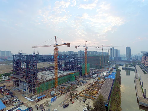
The column splice is where the design meets the crane two ways: the splice location is chosen so that no single column piece exceeds the lifting envelope of the site cranes (typical pieces of two to three storeys, 8–12 m), and the splice detail must transfer the full column force with the axial load and the bending moments present at that level. Welded box-to-box splices are full-penetration with backing bars removed or sealed where the joint is exposed; bolted splices use splice plates on the flanges with high-strength slip-critical bolts, sized so that the column force is carried by the plates and bolts while the web splice carries the shear transfer. The erection logic that follows: set the column piece at the survey grid, plumb with two orthogonal theodolites to the H/1,000 column verticality tolerance, and only then torque the splice bolts in the prescribed sequence. The frame is not stable storey by storey — it stabilises when the floor composite slabs are cast and the braced bays are closed — so the erection sequence plan and the temporary guying program are part of the permanent design documentation, and the owner’s schedule should treat the splice torqueing and slab casting as engineering gates, not site speed items.
Key Takeaways
- System selection is a height decision: moment frames to about 60–110 m, braced frames to about 180 m, frame–core hybrids to 300 m, mega frames beyond — with seismic intensity per GB 50011-2010 Table 6.1.1 trimming each band.
- Inter-storey drift governs sizing: the H/400 wind-serviceability limit of JGJ 99-2015 (H/300 under frequent earthquakes, H/50 elastoplastic) is the number that sizes the lateral system, not stress.
- P-Δ is real above 150 m: check the stability coefficient θ against 0.1/0.25, use minimum plausible gravity, and include both global P-Δ and member P-δ.
- Comfort is measured, not assumed: top-floor acceleration limits of 0.15 m/s² (residential) and 0.25 m/s² (office) at 10-year wind per GB 50009-2012, closed by shaping, damping or stiffness.
- BRBs turn bracing symmetry into money: a low-yield encased core dissipates several times the energy of a conventional brace for the same stiffness, cutting lateral system tonnage in high-seismic zones.
- Fire and floors are sequence decisions: R90–R120 protection and composite slabs with headed studs, with the slab casting sequence designed into the erection schedule from day one.
For a tall building programme — from 20 storeys to 300 m — our engineering team can review or produce the system selection, drift and comfort studies, brace layouts, and the fabrication package with fire and floor details co-ordinated. Contact our engineering team for a structural system feasibility study.
Need High-Rise Steel Structures Engineered and Fabricated to GB or AISC Practice?
With steel supplied for the twin 265 m Tianjin R&F towers and fabrication capacity for heavy box columns, outrigger trusses and composite floors, we deliver tall-building steel packages with the drift, comfort and brace analysis documented. Send us your scheme for a feasibility assessment.
Request a Consultation