
High-Strength Bolt Connection Quality Control: Full Process Guide
High-strength bolted connections are the backbone of modern steel structure fabrication. They transfer forces through friction between the connected plates (slip-critical connections) or through bolt shear and bearing (bearing-type connections). In either case, the connection's performance depends on a chain of quality control steps that begins at the steel mill and ends at the torque wrench on the construction site. A failure at any link in this chain — from surface preparation to bolt storage to tightening method — can compromise the connection's load capacity and, ultimately, the structure's integrity.
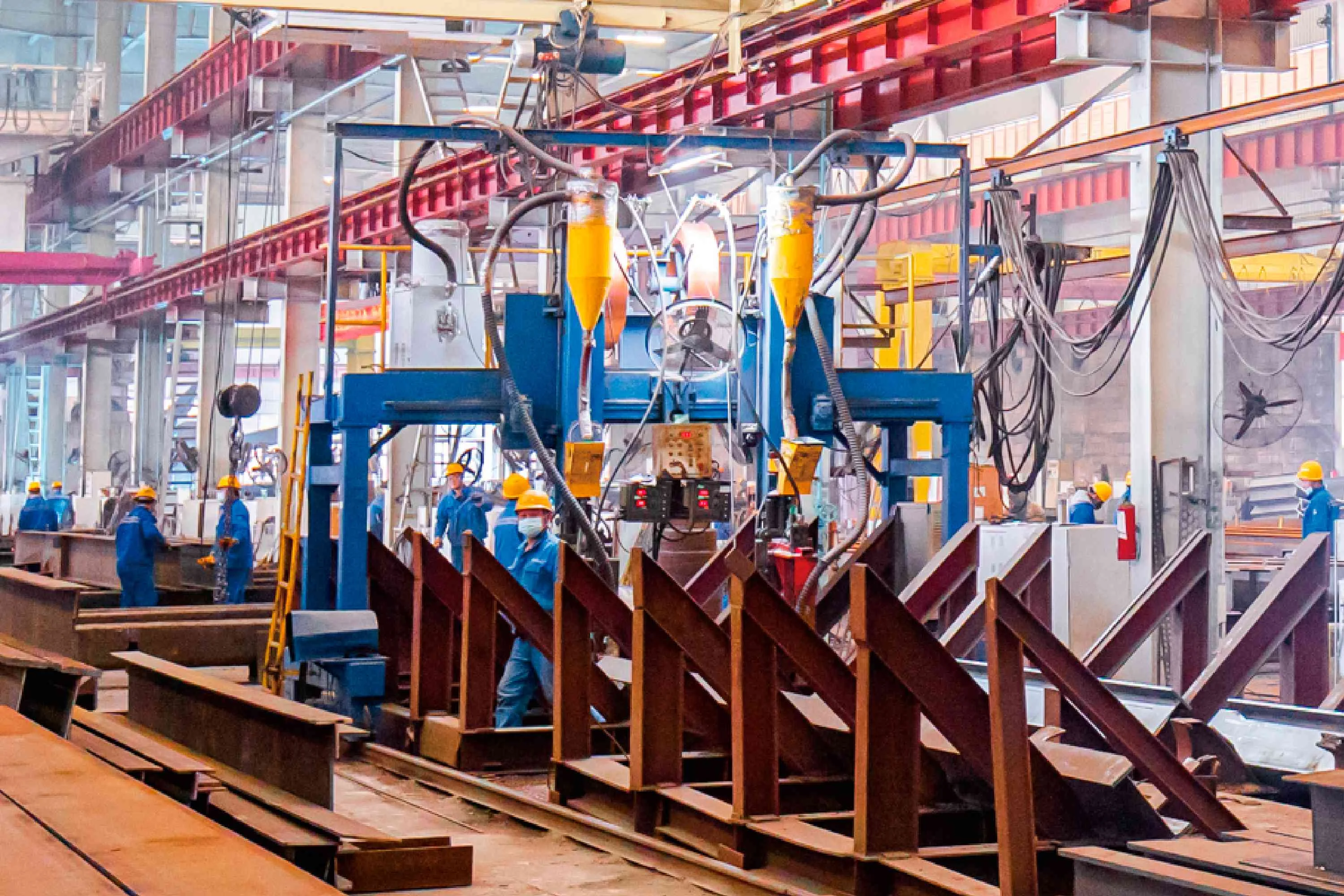
At Permanent Steel Structure, our manufacturing facility processes over 200,000 tonnes of steel per year, with high-strength bolted connections in virtually every project. Our Special-Class manufacturing qualification (see our qualifications page) requires a documented, audited quality control system for bolted connections. This guide shares the procedures and standards we follow, written for project owners, quality engineers, and contractors who need to understand what "good" looks like.
1. Friction Surface Preparation: The Foundation of Slip-Critical Connections
In a slip-critical connection, the load is transferred by friction between the faying surfaces (the surfaces in contact when the connection is clamped together). The friction resistance depends on the slip coefficient (μ), which is determined by the surface condition. GB 50017 and JGJ 82 specify the following standard slip coefficients:
- Class A (μ = 0.45-0.50): Sandblasted or shot-blasted surface with a roughness of Ra 12.5-50 μm. This is the highest standard and is required for connections where slip must be prevented under service loads (seismic connections, fatigue connections).
- Class B (μ = 0.40): Sandblasted surface with a subsequently applied protective coating (typically inorganic zinc-rich primer) not exceeding 80 μm dry film thickness. The coating must be fully cured and free of oil, grease, or moisture before assembly.
- Class C (μ = 0.30): Cleaned surface (wire-brushed or flame-cleaned) with visible rust. This is the lowest standard and is used only for connections where slip is acceptable under service loads.
Blast Cleaning Procedure
For Class A surfaces, we use abrasive blasting with steel grit (G24 or G40 grade) to a cleanliness level of Sa 2.5 (near-white metal) per ISO 8501-1. The blasting parameters are:
- Nozzle pressure: 0.6-0.7 MPa (85-100 psi)
- Abrasive velocity: 70-90 m/s
- Stand-off distance: 100-300 mm
- Angle of incidence: 70-90° for maximum roughness
After blasting, the surface roughness is verified using a replica tape (Testex) or a portable surface roughness gauge. The minimum acceptable roughness for Class A is Ra 12.5 μm. If the roughness is below this threshold, the surface must be re-blasted with coarser grit.
Surface Protection and Shelf Life
A blasted surface is reactive — it begins to oxidize immediately upon exposure to humid air. For Class A surfaces without protective coating, the surface must be assembled within 180 days of blasting if stored indoors in a dry environment, or within 2 days if stored outdoors. After this period, the surface must be re-blasted before use.
For Class B surfaces with zinc-rich primer, the coating provides surface protection, but the coating thickness must be controlled: if the DFT exceeds 80 μm, the slip coefficient drops below 0.40 because the coating itself becomes a slip plane. We verify DFT at five locations per connection plate using a magnetic gauge, with a maximum variation of 15 μm between readings.
Slip Coefficient Testing
For each project, we produce three test specimens from the same steel batch and with the same surface preparation as the production connections. These specimens are tested in a universal testing machine per GB/T 36332 to verify the actual slip coefficient. The test result must equal or exceed the design value. If a test fails, the entire batch of connection plates must be re-prepared.
2. Bolt Storage and Handling
High-strength bolts (Grade 8.8, 10.9, and 12.9 per GB/T 1231 or ISO 898) are precision products with specific metallurgy and heat treatment. Improper storage can degrade the bolt's mechanical properties and compromise the connection. The primary risk factors are moisture (causing hydrogen embrittlement in high-strength steels) and mechanical damage (nicking the thread or altering the head geometry).
Storage Conditions
Bolts, nuts, and washers must be stored in their original sealed packaging until immediately before use. The storage environment must maintain:
- Relative humidity: Below 60% to prevent moisture absorption into the packaging and subsequent condensation on bolt surfaces.
- Temperature: 10-35°C, with minimal daily fluctuation to prevent condensation from temperature cycling.
- Ventilation: Natural ventilation, no direct sunlight on storage containers.
For projects in humid environments (coastal areas, rainy seasons), we use desiccant packs inside bolt storage containers and monitor humidity with hygrometers. If humidity exceeds 60%, the storage area is dehumidified. Bolts that show visible rust are rejected — surface rust on a high-strength bolt can indicate hydrogen absorption, which cannot be reliably detected by visual inspection alone.
Batch Management and Traceability
Every bolt batch is identified by a lot number stamped on the container. The lot number links to a material certificate that documents the steel heat number, chemical composition, heat treatment, and mechanical test results (yield strength, tensile strength, elongation, CVN impact, hardness). This traceability is required by GB 50205 (Code for Acceptance of Construction Quality of Steel Structures) and is audited during our third-party qualification inspections.
Before use, each batch is sample-tested for hardness (Rockwell C scale), thread dimensions (go/no-go gauges), and visual defects (cracks, burrs, deformation). The sampling rate is 0.5% of the batch, with a minimum of 5 bolts. Any defect in the sample triggers 100% inspection of the batch.
3. Three Tightening Methods: Torque, Turn-of-Nut, and Indicator Washers
The objective of bolt tightening is to achieve a specified pretension (clamping force) in the bolt. The pretension creates the normal force on the faying surfaces that generates the friction resistance in slip-critical connections. GB 50205 and JGJ 82 specify three acceptable tightening methods, each with different accuracy, equipment requirements, and quality control implications.
3.1 Torque Control Method
The torque method uses a calibrated torque wrench to apply a specified torque, which is converted to pretension through the empirical relationship:
T = K · d · P
where T is the applied torque (N·m), K is the torque coefficient (typically 0.11-0.15 for galvanized bolts, 0.17-0.19 for black bolts), d is the bolt nominal diameter (mm), and P is the target pretension (kN). For a standard M20 10.9 bolt with a target pretension of 155 kN and K = 0.18:
T = 0.18 × 20 × 155 = 558 N·m
The torque method is the most widely used because the equipment is simple (a calibrated torque wrench) and the procedure is straightforward. However, the torque coefficient K is sensitive to lubrication, surface condition, and thread geometry, and can vary by 20-30% between bolts of the same batch. To control this variability:
- The torque wrench must be calibrated daily before use against a bolt tension calibrator (a hydraulic load cell that directly measures bolt pretension).
- Five bolts from each batch are tested to determine the actual torque coefficient, and the target torque is adjusted accordingly.
- The torque wrench must be recalibrated after every 200 bolts or every shift, whichever comes first.
The accuracy of the torque method is approximately ±15-20% of the target pretension, meaning the actual pretension can range from 80% to 120% of the target. This variability is acceptable for most structural connections but is insufficient for critical connections where the pretension must be controlled to within ±10%.
3.2 Turn-of-Nut Method
The turn-of-nut method achieves pretension by rotating the nut a specified number of turns from a snug-tight condition. The premise is that the bolt elongates predictably with rotation, and the pretension is proportional to the bolt elongation within the elastic range.
The standard rotation amounts for different bolt lengths and diameters are specified in JGJ 82:
| Bolt Length/Diameter Ratio | Rotation (from snug-tight) | Approximate Pretension |
|---|---|---|
| ≤ 4d | 1/3 turn (120°) | 0.70 Pu |
| 4d to 8d | 1/2 turn (180°) | 0.75 Pu |
| 8d to 12d | 2/3 turn (240°) | 0.78 Pu |
| > 12d | 1 turn (360°) | 0.80 Pu |
where Pu is the bolt ultimate tensile strength. The turn-of-nut method is more accurate than the torque method (±10-15% of target) because it controls the bolt elongation directly, rather than inferring pretension from torque. It is also less sensitive to lubrication and thread condition. However, it requires that the snug-tight condition is achieved consistently (defined as the point where the wrench cannot be turned by hand), which requires a trained operator.
The turn-of-nut method is our preferred method for field assembly of slip-critical connections in our steel components and structural frame projects. We mark the nut position with a paint stripe after snug-tightening, then rotate to the marked position, providing a visual verification that the rotation was completed.
3.3 Direct Tension Indicator (DTI) Washers
DTI washers are mechanical devices that provide a direct, visual indication of bolt pretension. The most common type is a hardened washer with protrusions (bumps) on one face. As the bolt is tightened, the protrusions are compressed against the connected plate. When the protrusions have flattened to a specified gap (measured with a feeler gauge), the bolt has reached the target pretension.
The advantage of DTI washers is independent verification: an inspector can check whether the bolt was properly tightened by measuring the gap, without re-tightening or loosening the bolt. This makes DTI washers the preferred method for connections that will be inspected by third parties or where the tightening was performed by a subcontractor.
The accuracy of DTI washers is ±5-10% of target pretension — the best of the three methods. The disadvantage is cost: DTI washers add approximately 15-25% to the bolt assembly cost, and the feeler gauge inspection is time-consuming. We use DTI washers for the most critical connections (seismic connections, primary load-path connections, connections subject to fatigue loading).
4. Inspection and Verification
After all bolts in a connection are tightened, the connection must be inspected and documented. The inspection protocol per GB 50205 includes:
Torque Verification (Torque Method)
A calibration wrench is used to re-apply the target torque to 10% of the bolts (minimum 10 per connection). If the nut does not turn when the target torque is applied, the bolt is accepted. If the nut turns, the bolt is re-tightened to the target torque plus 5%, and the connection is re-inspected. If more than 5% of the sampled bolts fail, the entire connection must be re-tightened.
Rotation Verification (Turn-of-Nut Method)
The paint stripe marking is visually inspected on 100% of bolts. Any bolt where the stripe does not align with the expected rotation is re-tightened. Additionally, 10% of bolts are checked with a torque wrench to verify that the residual torque exceeds 80% of the target torque.
Gap Verification (DTI Method)
A feeler gauge (0.5 mm for standard DTI washers) is used to check 100% of bolts. The gauge should not pass between the washer and the connected plate at more than 1 of the 4 protrusion locations. If the gauge passes at more than one location, the bolt is under-tightened and must be re-tightened.
Ultrasonic Bolt Inspection
For the most critical connections (nuclear facilities, seismic fuse connections, bridge tension members), we use ultrasonic bolt inspection to directly measure the bolt's axial stress. An ultrasonic transducer is coupled to the bolt head, and the time-of-flight of an ultrasonic pulse through the bolt is measured. The bolt's elongation (and hence its stress) is calculated from the change in time-of-flight compared to the unstressed bolt.
Ultrasonic bolt inspection has an accuracy of ±3-5% of the target pretension — the highest of any method. It is also the only method that can verify the pretension after the connection has been loaded, which is critical for connections where the load path changes during construction (for example, when shoring is removed or when the structure is jacked into its final position).
The limitation is cost: ultrasonic bolt inspection requires specialized equipment and trained technicians, and costs approximately 50-100 RMB per bolt. We use it for connections where the consequence of failure is high and where other inspection methods are insufficient.
5. Common Failure Modes and Prevention
In our 25+ years of steel structure fabrication, we have identified five common failure modes in high-strength bolted connections. Each is preventable with proper quality control:
Failure Mode 1: Slip Under Service Load
Symptom: The connection shifts or "pops" under load, causing visible displacement and a loud noise. Cause: Insufficient pretension (from inaccurate torque, worn wrench calibration, or bolt relaxation over time) or degraded friction surface (rust, oil, or paint on the faying surface). Prevention: Verify pretension with the most accurate method feasible for the connection's importance; protect faying surfaces from contamination; re-torque connections after 48 hours to account for relaxation (typically 2-5% of initial pretension).
Failure Mode 2: Bolt Fracture
Symptom: The bolt shank or head fractures, usually without warning. Cause: Hydrogen embrittlement (from moisture exposure of high-strength steel during storage), over-tightening (exceeding the bolt's ultimate strength), or fatigue from cyclic loading. Prevention: Control storage humidity; calibrate tightening equipment; replace bolts that show signs of corrosion; design connections for the fatigue load range.
Failure Mode 3: Thread Stripping
Symptom: The nut threads strip, allowing the nut to rotate freely without building pretension. Cause: Mismatched bolt and nut thread classes, damaged threads from improper handling, or oversized holes that allow the bolt to tilt. Prevention: Verify thread compatibility before assembly; protect threads during transport and storage; limit hole oversize to the values in JGJ 82 (1.0 mm for M16-M22, 1.5 mm for M24-M27).
Failure Mode 4: Galling (Cold Welding)
Symptom: The nut seizes on the bolt during tightening, preventing further rotation. Cause: High contact pressure and relative motion between stainless steel or galvanized surfaces, causing local welding. Prevention: Use anti-galling lubricant (molybdenum disulfide or copper-based) on threads; use different hardness nuts and bolts (at least 10 HRc difference) for galvanized connections.
Failure Mode 5: Connection Plate Deformation
Symptom: The connected plates deform (bend or warp) at the bolt pattern, causing an uneven load distribution. Cause: Bolt pattern too close to the plate edge (edge distance less than 1.5d), excessive bolt spacing, or plate thickness insufficient for the pretension. Prevention: Follow minimum edge distance and spacing requirements (GB 50017: minimum edge distance 1.5d, minimum spacing 3d); verify plate thickness against the bolt pretension bearing capacity.
6. Documentation and Quality Records
Quality control in bolted connections is only as good as the documentation that proves it was done. For each connection, our quality records include:
- Material certificates for bolts, nuts, and washers (linked by lot number)
- Slip coefficient test reports for the friction surface
- Daily torque wrench calibration records
- Bolt tightening logs (connection ID, bolt ID, method, verification result)
- Nonconformance reports for any bolts that failed verification
- Third-party inspection reports (for connections subject to independent verification)
These records are retained for the design life of the structure (minimum 50 years) and are available to project owners upon request. Our manufacturing capabilities include a fully digital quality management system that tracks each bolt from receipt through installation.
Conclusion
High-strength bolted connection quality is a chain of interdependent processes: surface preparation, bolt storage, tightening method, inspection, and documentation. A weakness at any link can compromise the connection's load capacity. The key principles are:
- Prepare the surface correctly: Blast to Sa 2.5, verify roughness, protect from contamination, and test the slip coefficient on each batch.
- Store bolts properly: Controlled humidity, sealed packaging, traceable lot numbers, and rejection of corroded bolts.
- Choose the right tightening method: Torque for standard connections, turn-of-nut for accuracy, DTI washers for critical connections, and ultrasonic for the most demanding applications.
- Inspect and document: Verify every connection, record the results, and retain the records for the structure's design life.
- Understand failure modes: Slip, fracture, thread stripping, galling, and plate deformation are all preventable with proper procedures.
Our Special-Class manufacturing qualification and 25+ years of experience mean that these procedures are not theoretical — they are daily practice on our production floor. If your project requires high-quality bolted connections with full documentation and traceability, contact our engineering team to discuss your requirements.
Need Expert Engineering for Your Steel Structure Project?
Our engineers bring 25+ years of experience in steel structure fabrication with Special-Class manufacturing qualifications. Every bolted connection we produce is documented, tested, and traceable. Send us your project requirements today for a quality-controlled solution.
Request a Consultation