
Portal Frame Design Guide: Connections, Optimisation and Steel Consumption Benchmarks
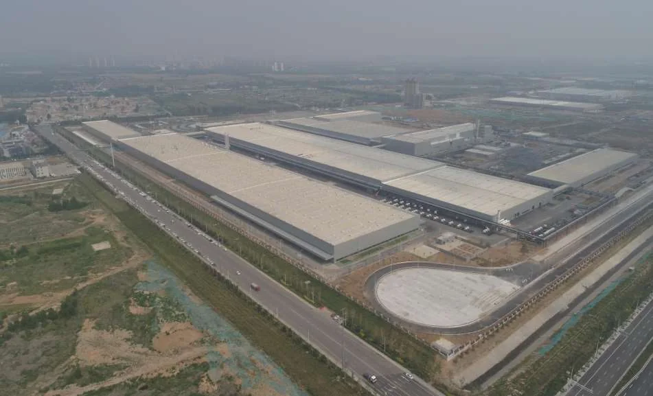
For warehouses, factories, workshops and logistics buildings, the single-storey portal frame is the workhorse of steel construction worldwide. It is also the product where steel consumption, fabrication hours and erection speed vary most between suppliers, because the frame geometry is not set by an architect — it is set by the engineer's choices of member taper, connection type, base fixity and bracing layout. On a 5,000 m² industrial building, a difference of 8 kg/m² in the structural steel means roughly 40 t of steel and a six-figure swing in the contract, so owners and contractors reviewing a portal frame design should be able to interrogate every number in this article.
This guide follows the Chinese light portal frame standard GB 51022-2015 (Standard for Design of Steel Structure of Light-Weight Buildings with Gabled Frames), cross-references where relevant to GB 50017-2017 for general steel design, and to AISC 360-16 and Eurocode 3 (EN 1993-1-1 and EN 1993-1-8) for projects tendered under North American or European practice. The consumption benchmarks below come from our own fabrication records for portal frame buildings in the 12 m to 36 m span band, fabricated in our Xuzhou workshops including components supplied to large industrial programmes such as the Guangzhou Baiyun International Airport Phase III expansion (450,000 m², 42,000 t of steel).
Five decisions control the result: frame layout and stability system, moment connection detailing, section taper, column base fixity, and the secondary steel (purlins, girts and bracing). We cover each in turn, then give the steel consumption tables.
1. Frame Layout and the Stability System
The portal frame itself — two columns and a rafter pair with knee connections — resists vertical load in bending, but its out-of-plane stability depends entirely on secondary members. The transverse (gable-to-gable) direction is stabilised by the frames acting with the roof bracing; the longitudinal direction is stabilised by the columns working with the wall bracing. Remove the bracing from the model and the frame is a mechanism in one direction; this is why the bracing layout must be fixed before member sizing, not after.
- Column bracing (wall plane): X-bracing in at least two bays, typically angle L75×6 or high-tensile round bar φ24 mm with turnbuckles, placed in the first or second bay from each gable.
- Roof plane bracing: horizontal X-bracing in the first roof bay and every second bay beyond, with rigid tie rods (φ89×3.5 to φ114×4 CHS) at ridge and eave lines to distribute forces.
- Fly braces (knee braces): small angles connecting the rafter bottom flange to each purlin line, preventing compression-flange lateral buckling between brace points. Their omission is a common and serious shop-drawing error.
- Wind columns: for gable lengths beyond about 30 m, intermediate wind columns transfer gable wind load to the roof and floor diaphragms, usually spanning full height with pinned ends.
- Crane buildings: add crane columns or heavier frames, an extra longitudinal tie girder at the crane rail level, and crane runway tolerances that govern the whole drift budget.
Governing Load Cases in Practice
Three load cases govern nearly every portal frame, and scheme-stage drawings should show them all. The dead plus live case sizes the rafter at mid-span and the column in the apex region; the wind uplift case reverses the rafter bending and governs the purlins, the base uplift and often the column base plate; and the windward drift case with wind on the gable end sizes the longitudinal bracing and the end-frame columns. On frames with cranes, the crane wheel loads with impact factors add the eccentric moment at the column step that frequently governs the lower column section, and the crane surge (lateral) case governs the column base shear and the foundation anchors. The frame report should state the governing combination for every member line, because the owner’s value engineering conversation — shall we reduce the bay spacing, deepen the rafter, or add one brace bay — can only be answered with that table in hand. GB 51022-2015 load factors (1.3 dead, 1.5 live, 1.5 wind in the strength combinations) apply in China; exported frames follow EN 1990 or ASCE 7 factors, and the difference matters mostly in the wind case, where the partial factor spread changes the anchor design.
Frame Geometry Rules of Thumb
Three geometric ratios start every preliminary scheme, and their values are remarkably stable across codes. The rafter slope of 1/10 to 1/20 balances snow shedding against interior height and cladding cost; the frame spacing of 6.5–8.5 m is set by the purlin economy (purlin weight climbs steeply above 8 m); and the frame span-to-depth ratio — rafter depth at the haunch of span/30 to span/40 for buildings without cranes — gives the starting section before optimisation. A 30 m span therefore opens with a 750–1,000 mm haunch depth, and the tapered section analysis in Section 3 then trims weight from there. These rules produce a scheme that is within 5–10% of optimum before any software is opened, and they anchor the value-engineering conversation when the architect changes the bay spacing late in the schedule.
2. Moment Connections: Haunches, End Plates and High-Strength Bolts
The knee joint (column-to-rafter) and ridge joint carry the full frame moment and must be detailed as rigid moment connections. In Chinese practice these are made with extended end plates connected by high-strength bolts grade 10.9s (M20 to M24 typically, designed as slip-resistant frictional-type joints with pretension per GB 50017-2017), plus a haunch at the knee: a tapered extension of the column web and flange into the rafter zone, 0.15–0.25 of the rafter span where moments are highest.
Three details decide whether the connection actually delivers the modelled stiffness. First, the end plate must be stiff enough to avoid prying action consuming the bolt capacity — plate thickness is usually 20–25 mm and bolt rows are proportioned so that the outermost bolt row carries no more than its design tension including prying. Second, column and rafter flanges at the connection need transverse stiffeners aligned with the bolt rows; without them the reduced web thickness yields in bearing long before the bolts. Third, weld detailing: flange butt welds full penetration at the splice, web fillets sized per GB 50661, and weld inspection by ultrasonic testing for all full-penetration butt welds at moment splices.
For European and US practice the same joint concept is validated differently — EN 1993-1-8 component method or AISC prequalified connections — but the geometry habits above transfer directly.
Connection Detailing Rules That Survive the Shop
Moment connections fail in two ways: by not delivering the design moment, and by being unbuildable within tolerance. The rules that keep both failures out of the shop drawings are few and fixed. The end plate is thicker than the beam flange it transfers (16–25 mm typical), the bolt rows are placed close to the flanges where the plate is most stressed, the haunch depth follows the rafter slope so that the splice lands where the moment is low, and the flange-to-plate welds are full-penetration with the root verified by magnetic-particle or ultrasonic testing. High-strength bolts in moment connections are slip-critical where any reversal or vibration exists, and the connection stiffness is assumed in the frame analysis — a pinned assumption on a moment-connected frame underestimates drift and overstates the joint freedom.
3. Tapered Section Optimisation
The defining feature of the light portal frame is the tapered, welded H-section: the web depth varies linearly from the column base (shallow) to the knee (deep) and from the knee back to the ridge (shallow). The bending moment envelope of the frame is roughly triangular, and the section follows it. A well-optimised tapered frame delivers 10–20% less steel than a prismatic frame of equal capacity, which is why GB 51022-2015 is written around variable-depth members and allows their capacity verification by elastic analysis with effective section properties.
- Web depth ratio: depth at knee to depth at end of 2.0–2.5× is the practical optimum; beyond that local buckling and fabrication cost eat the savings.
- Local buckling control: web and flange slenderness limits are checked per GB 51022-2015 Section 6: when the web height-to-thickness ratio exceeds 80ε (where ε = √(235/fy)), intermediate stiffeners or a post-buckling (tension-field) verification is required; flange outstand-to-thickness is kept below 15ε.
- Materials: Q355B and Q355C welded plate sections are the standard, with flange thicknesses of 10–16 mm and web thicknesses of 6–10 mm (minimum 6 mm for erection robustness).
- Target utilisation: an optimised frame runs chords at 0.80–0.90 utilisation at the controlling combination; anything below 0.7 indicates the section was not adapted to the envelope.

4. Column Bases: Pinned or Fixed, and Anchor Bolt Detailing
Base fixity is a cost lever most owners never see. A pinned base — a base plate 350–450 mm square with four M24–M30 anchor bolts and no web stiffeners — passes zero moment to the foundation and keeps the column section economic at the base. A fixed base in the same frame adds an 8–10 bolt group, a heavier plate with stiffeners, column web stiffeners at the base and a larger, more heavily reinforced foundation. The extra cost is justified only when the frame drift budget forces it (crane buildings, tall eaves above 10 m, high wind zones) or when foundations are expensive and the moment capacity lets the frame deflect less.
Anchor bolt detailing follows the same rules in every code family: embedment of 25–35 bolt diameters with a hook, anchor plate or T-head; a minimum clear edge distance; grout space of 40–50 mm filled with non-shrink grout after erection; and a check for wind-uplift tension on the windward side, which at 0.6–0.9 kN/m² roof suction can govern the anchor bolt group in light roofs. Anchor bolts are not high-strength bolts: they are typically Q355B or 8.8-grade material, tension-checked with their own careful treatment of the coupled stiffness between the bolt, plate and grout.
Column Base Choices and Anchor Bolt Tolerances
Pinned bases use two anchor bolts and a base plate thick enough to distribute the small eccentric moments of erection; fixed bases use four to eight bolts, a stiffer plate, and often haunched gussets at the column flanges. Whichever is specified, the anchor bolt template tolerance is the number the whole frame depends on: GB 51022-compliant practice holds anchor group position to ±2–3 mm and bolt projection to ±10 mm, with the base plate slotted or re-machined where the template drifts. Grouting with high-strength nonshrink grout to a 25–50 mm bed is mandatory to close the gap between the steel and the concrete, and the grout test cube is part of the QA record before erection loads are accepted.
The fixed base also changes the frame behaviour upstream: a moment-resisting base fixes the column at the floor line, raises the frame stiffness against wind and crane surges, and reduces the rafter moment at the apex. Owners should expect the frame report to state which base assumption was used and to re-verify it against the anchor detail, because a report assuming fixed bases on pinned-base details understates drift and overstates member economy.
5. Purlins, Girts and Secondary Steel
Secondary steel commonly adds 5–8 kg/m² to the frame weight and is the cheapest place to save money badly. Purlins and girts are cold-formed Z or C sections (e.g., Z220 to Z300, 2.0–3.0 mm base steel, S350GD+Z with Z275 galvanising), designed to GB 50018-2015 for cold-formed steel, with continuous lapped Z-purlins over the rafters at 1.2–1.5 m spacing. The cheapest purlin is never the cheapest roof: deflection limits of span/150 to span/200, fastener pull-out under suction, and handling stiffness all drive the choice, and a 1.5 m spacing with a heavy section is usually dearer than 1.2 m with a light one once brackets and fasteners are counted.
Rationalise the secondary steel once and for all in the tender: one purlin section, one girt section, one Z-section spacing, one corner/trim detail. It is the fastest cost reduction available in the design.
Purlin and Girt Design Workflow
Zed purlins are sized to GB 51022 rules for wind uplift — the governing case for roof purlins in most of coastal China — with deflection limits of span/180 under dead plus live load and span/150 under live load alone. The uplift case is surprising to owners: wind suction reverses the purlin bending and puts the compression flange on the bottom, unsupported by the sheeting, which is why the purlin-to-rafter connection must be detailed for that sign of load, with the cleat stiffened to carry the uplift reaction into the rafter without local web distortion. Anti-sag rods between purlin rows control the torsion of the Z-section under combined bending and twist, and the rod tension is part of the purlin check, not an afterthought.
6. Steel Consumption Benchmarks
The ranges below are for complete primary steel (tapered frames, bracing, purlins, girts and fly braces) excluding cladding, insulation and interior partitions, for normal roof loads of 0.3–0.5 kN/m² and moderate wind and snow. Values are for Q355B/Q355C and typical eave heights; every 10 m of added eave height adds roughly 3–6 kg/m².
| Span (m) | Typical eave height | Primary steel (kg/m²) | Notes |
|---|---|---|---|
| 8 – 14 | 6 – 8 m | 18 – 25 | Light warehouses, workshops, no crane |
| 14 – 24 | 8 – 10 m | 22 – 30 | Standard logistics and factory bays |
| 24 – 30 | 9 – 12 m | 25 – 35 | Heavier roofs, higher eaves |
| 30 – 45 | 10 – 14 m | 30 – 45 | Multi-bay, crane or equipment loads |
Two corrections apply in practice. Heavy snow districts (design snow ≥ 1.5 kN/m²) add 5–10 kg/m²; crane buildings add a further 5–15 kg/m² including the crane runway girders. A tender that quotes outside these bands, either far above or far below, is a tender that should be asked to explain its numbers — the bands above are what efficient fabrication achieves.
7. Code Basis: GB 51022, AISC 360 and Eurocode 3 at a Glance
GB 51022-2015 is the governing standard for light portal frames in China and differs from the international codes in two respects that matter in tenders. First, load combinations follow the Chinese load code family (GB 50009): the windward loading works with shape factors and partial factors specific to light roofs, and the code consciously accepts more generous serviceability limits because light frames are deformation-tolerant: column top drift under wind up to about H/60 for frames without cranes (tighter H/120–H/180 is commonly specified where cladding or door mechanisms are sensitive), rafter deflection of L/180–L/240 depending on the load case, and crane buildings governed instead by rail-level drift limits near H/400. AISC 360-16 approaches the same structure through LRFD or ASD with the 1/400 storey-drift tradition for cladding-sensitive buildings, while Eurocode 3 relies on EN 1993-1-1 sway-check rules with an explicit initial imperfection of span/200 to h/200 applied in the model. All three converge on the same end: the member sections are set by the drift and stability envelopes, not by stress.
When we fabricate to multiple code families, one rule keeps the shop drawings consistent: the modelling basis (joint fixity, brace stiffness, imperfection) is fixed first, approved by the owner's engineer, and only then is steel sized. Changing the basis after fabrication starts is the most expensive error in light steel building.
Reading the Code Family for an Export Project
When a portal frame is fabricated in China for export, the design basis must be stated once and honoured everywhere: the frame analysis per GB 51022 uses Chinese load combinations and capacity factor formats; a Eurocode basis imports EN 1990 load combinations, EN 1993-1-1 member checks with γM0 = 1.00 / γM1 = 1.10, and the lateral-torsional buckling verification of EN 1993-1-1 clause 6.3.2; an AISC basis uses LRFD load factors and the AISC 360 Chapter F beam and Chapter E column checks with φb = 0.90 and φc = 0.90. The shop drawings, weld classes, bolt specs and paint specification must each follow the same code family — a frame analysed to Eurocode but detailed with China-specific weld symbols and bolt markings is a compliance risk no certificate can cure, and the export checklist should verify code consistency line by line before fabrication starts.
Key Takeaways
- The stability system is designed before the members. Bracing bays, tie rods and fly braces are part of the primary structure; omitting them in the model makes every member wrong.
- Moment connections deliver stiffness only when detailed. End plates 20–25 mm, stiffeners over the bolt rows, full-penetration flange welds and slip-resistant 10.9s bolts are the package, not options.
- Taper the section to the moment envelope. A 2.0–2.5× web depth ratio with local buckling control saves 10–20% of steel versus a prismatic frame.
- Pinned bases are the default, fixed bases the exception. Use fixity, anchors and foundations as one budget: crane frames and tall eaves justify fixed bases; plain warehouses usually do not.
- Benchmark your tender: 18–25 kg/m² at 8–14 m span, 25–35 kg/m² at 24–30 m, 30–45 kg/m² at 30–45 m span, with snow and crane corrections.
- Fix the analysis basis first. Drift limits, brace stiffness and initial imperfections must be agreed before section sizing, and never changed after fabrication begins.
Send us your building footprint, eave height, crane requirements and local wind and snow data, and our engineering team will return a portal frame scheme with member sizes, connection details, bracing layout and a steel consumption estimate that you can benchmark against the tables above. Contact our engineering team for the preliminary design study.
Need Your Portal Frame Building Designed and Fabricated to GB, AISC or Eurocode Practice?
From single-bay warehouses to multi-bay crane buildings, we provide complete engineering, fabrication and erection support with steel consumption benchmarks you can verify. Send us your layout for a feasibility assessment and budget.
Request a Consultation