
Space Frame Design Guide: Grid Types, Node Selection and Engineering Workflow
For a railway station concourse, exhibition hall, sports arena or enclosed bulk-storage yard, the roof is often the largest and longest-lead structural package on the project. A space frame — a double-layer grid of steel tubes working in three dimensions — remains one of the most efficient solutions for spans between 30 m and 120 m because its load path is short, its self-weight per square metre is low, and its redundancy means a single member failure does not compromise the whole system. But the margin between an economical grid and an over-specified one is decided very early: grid topology, node type, member slenderness and grid depth are fixed in the first two weeks of design and are almost impossible to change economically afterwards.
This guide is written for project owners, design engineers and contractors who need to specify, evaluate or peer-review a space frame before steel is cut. It follows the requirements of the Chinese space frame code JGJ 7-2010 (Technical Specification for Space Frame Structures), the steel design standard GB 50017-2017, and cross-references Eurocode 3 where projects are tendered to European practice. The recommendations reflect structures we have fabricated and erected in our Xuzhou workshops, including large-span covers where grid depth, node capacity and erection sequence were the controlling parameters.
The article covers four decisions that drive 80% of the cost and schedule: grid type, node system, member and depth proportioning, and the analysis workflow used in SAP2000, MIDAS Gen and ANSYS.

1. Grid Topology: Two-Way, Diagonal and Three-Way Configurations
JGJ 7-2010 Chapter 4 classifies double-layer grids primarily by their in-plane layout. The three families that cover nearly all practical projects are the two-way orthogonal grid, the diagonal-on-square grid and the three-way grid, the Chinese terms for which are used throughout JGJ 7-2010. Each produces a different stiffness distribution, a different node count and a different fabrication cost, so the choice should follow the building plan and support condition rather than habit.
- Two-way orthogonal (orthogonal grid, 90°). Members run in two perpendicular directions with a square plan module. This is the default for rectangular plans with perimeter or grid supports in the 30–90 m range. It produces the lowest node count per square metre, the simplest member lengths and the most repetitive fabrication, which is why it is also the most economical to manufacture.
- Two-way diagonal (grid rotated 45°). The same orthogonal members laid at 45° to the plan axes. Because the diagonal reaches the boundary directly, the grid is noticeably stiffer at the edges and transfers loads into perimeter supports more evenly. It is a good choice when the roof is supported on four sides only, or when deflections at the corners of a rectangular plan are controlling.
- Three-way grid. Members run in three directions 120° apart, forming triangular cells. The stiffness is nearly isotropic, which suits spans beyond 80 m, irregular plans, heavy point supports (columns at 12–24 m spacing) and roofs carrying large equipment loads. The trade-off is a higher node count, shorter average member lengths and more shop cutting hours.
| Grid type | Typical span range | Module guidance | Key characteristic |
|---|---|---|---|
| Two-way orthogonal | 30 – 90 m | 3 – 6 m square | Lowest node count, most repetitive fabrication |
| Two-way diagonal | 40 – 80 m | 3 – 6 m at 45° | Stiffer at edges, better for perimeter supports |
| Three-way | 80 m and above | 2.5 – 4.5 m | Isotropic stiffness, suits heavy or point loads |
2. Node Selection: Bolted Sphere, Welded Hollow Sphere and Hub Nodes
The node is where the cost is hidden. Node hardware typically accounts for 15–25% of the total steel tonnage of a space frame, and it decides whether field erection is a bolting operation or a welding operation. Per JGJ 7-2010, three systems dominate: the bolted sphere node, the welded hollow sphere node, and the hub (sleeve) node used in lighter international grids.
Bolted Sphere Node
The bolted sphere node connects each member through a high-strength bolt (grades 10.9S, M12 to M64, per GB/T 16939) screwed into a forged sphere, with the bolt force transferred to the tube through a cone or sleeve. It requires no field welding at all: members arrive pre-cut at exact length with the cone and bolt pre-assembled, and the crew simply screws them into the spheres. This makes it the fastest and most weather-independent system, and it is the default for our industrial roofs and export projects where site welding is not available. The capacity is limited by the bolt grade: heavily loaded chord members near supports may exceed M56–M64 bolt capacity and will push the designer toward a welded node or a steel-ribbed (stiffened) sphere.
Welded Hollow Sphere Node
The welded hollow sphere is a hemispherical shell pair welded into a sphere, with each tube full-penetration welded to the sphere surface. It carries higher forces than a bolted node of equal size, which is why support zones, heavy chord paths and large-span three-way grids typically use it. All welds must be made per a qualified procedure (GB 50661) and inspected, and sphere diameters are sized so that the tube-to-sphere angle is kept practical. For loads beyond the plain sphere capacity, a ribbed (internally stiffened) sphere adds up to 40–50% capacity at modest extra cost.
Hub (Sleeve) Nodes
Hub-type nodes with cast or machined connectors and through-bolts are common in North American and European light grids. They offer excellent tolerance control and are re-usable by nature, but the castings are expensive and the system has a lower force ceiling per node, so we specify them mainly when the project owner's basis of design mandates a proprietary connector.
| Node type | Connection method | Typical member range | Site assembly |
|---|---|---|---|
| Bolted sphere | 10.9S bolt, GB/T 16939 | Tube D 60–180 mm | All-bolted, no field welding |
| Welded hollow sphere | Full-penetration butt weld | Tube D 76–219 mm | Shop or site welding + NDT |
| Hub / sleeve | Machined hub + through-bolt | Tube D 48–114 mm | All-bolted, proprietary castings |
Node Selection Impact on Erection Method
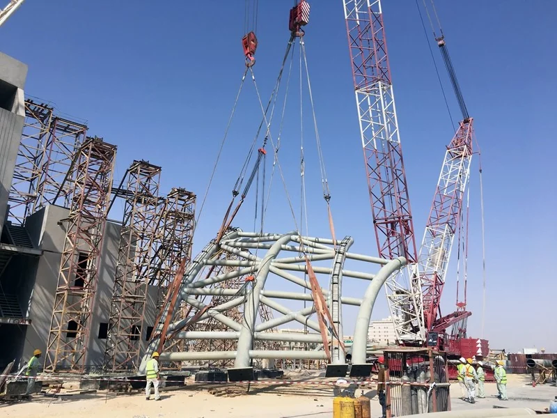
The node type decides the erection story as much as the analysis: bolted sphere grids are assembled piece-by-piece in the air with spud wrenches and small scaffolding towers, welded hollow sphere grids are pre-assembled in the workshop into large sub-assemblies (typically 400–900 m²) and lifted with cranes or jack-up equipment, and hub systems ship with pre-drilled sleeves that bolt quickly on site. For a project with a severe site window — like the 229 m clear-span coal storage structure we delivered, where air work above the stockpile was tightly constrained — the node choice was driven by erection logic first and cost second. The discussion belongs at scheme stage: the drawing that locks the node type has already locked the method statement.
3. Member Sizing and Slenderness Limits
Space frame members are almost always circular hollow sections (CHS): they have equal stiffness about every axis, a low drag coefficient for wind, and the smallest weld perimeter at the node for a given area. Typical chords and bracing range from φ60×3.5 mm up to φ219×12 mm in Q355B or Q355C (fy = 355 N/mm² up to 16 mm thickness), with wall thickness kept above 3 mm to make the node weld practical.
The controlling member check for a compression chord is almost always stability, and the code limits are explicit. JGJ 7-2010 Clause 5.1.4 sets the member slenderness limits: 180 for compression members, 400 for tension members, and 250 for tension members directly carrying dynamic loads. Support-adjacent chords are commonly held to 150 to prevent premature buckling of the most highly loaded members. The stability reduction factor φ is calculated over the full member length about either axis (for CHS the two radii are identical), using curve a or b of GB 50017-2017 depending on the tube forming process and wall thickness.
4. Grid Depth and Module Proportioning
Grid depth is the single most influential parameter for both stiffness and weight. For a double-layer orthogonal or diagonal grid, the practical band is grid depth = span / 12 to span / 16, with JGJ 7-2010 accepting 1/10 to 1/18 depending on load, support type and node system. At 60 m span, that is a 4.0–5.0 m deep grid; at 90 m, 5.6–7.5 m. Going deeper than 1/12 buys stiffness at a heavy penalty in brace length and node count; shallower than 1/16 forces chords into ever-larger sections and usually costs more steel, not less.
The plan module follows the roof build-up. A module of 3–6 m matches standard purlin and cladding spans, keeps chord lengths economic and limits the number of nodes. There is a well-known trade-off: halving the module roughly doubles the node count (and shop hours) while cutting member sizes only modestly, so owners should treat proposals with modules below 2.5 m or above 6 m with a request for justification.
Practical Depth Ranges by Span
For double-layer grid roofs, the structural depth — the distance between the top and bottom chord planes — is the most powerful single sizing lever. Practice and JGJ 7-2010 design guidance converge on a depth-to-span ratio of 1/12 to 1/16 for square and near-square grids, with ratios below 1/16 reserved for lightly loaded grids or where deflection is not the binding constraint. A 60 m grid roof therefore uses a nominal 4.0–5.0 m depth, and the depth choice must be locked before member sizing begins, because it changes the chord forces, the node angles and the entire shop detail universe.
Depth check: h ≥ L/16 → 60 m span needs h ≥ 3.75 m minimum; typical design band 4.0–5.0 m (L/15 to L/12)
Within the band, the module follows the depth: a module of 0.8–1.0 times the depth is typical, so a 4.5 m deep grid uses 3.6–4.5 m cells. The interaction between depth, module and node count is where grid optimisation actually happens — it is an iterative loop, not a single formula, and each iteration changes the bolt count on every node.
5. Deflection Control
JGJ 7-2010 limits roof space frame deflection to span / 250 under dead plus live load. Where the grid supports a floor, mechanical platforms or partitions, we apply the more stringent span / 300 to span / 400 limits from GB 50017-2017 for floor structures. Deflection is rarely the check that sizes members in a well-proportioned grid — stability is — but it becomes controlling at very shallow depths or when long cantilevers exist.
Two practical measures cost almost nothing and should appear in every specification. First, specify camber: fabricating the grid with a pre-set rise of 0.5–1.0 times the dead-load deflection brings the finished roof to a level or slightly crowned profile. Second, decide the support boundary honestly in the model: a grid assumed simply supported but welded to a stiff edge ring will attract forces the design never accounted for, usually showing up as unexpected weld or sphere stresses at the boundary nodes.
6. Analysis Workflow: SAP2000, MIDAS Gen and ANSYS
The modelling sequence below is the one we use for every space frame, and it applies with minor variations in SAP2000, MIDAS Gen or ANSYS Mechanical. Each step produces a checkable quantity; nothing is left to the black box.
- Geometry generation. Build the grid from the topology rule (module, depth, boundary). Check for duplicate nodes, short members and node-to-node connectivity before any load is applied.
- Member and node idealisation. Bolted sphere nodes are modelled as pinned (truss) members with axial force only. Welded sphere nodes are modelled as continuous (beam) members or as pinned members with rotational stiffness at heavy nodes, matching the JGJ 7-2010 treatment of the two systems.
- Loads per GB 50009-2012. Dead, imposed, snow/ice, wind (including suction on large flat roofs), thermal actions (±30°C is a common band) and seismic, with the code load combinations applied at the ULS and SLS levels.
- Global analysis. First-order elastic analysis is usually sufficient for deep grids; for shallow or thin lattice shells, run the second-order (P-Δ) analysis and perturbation check required by JGJ 7-2010, with an initial geometric imperfection of span / 300.
- Member verification. Axial capacity and stability per GB 50017-2017, using the slenderness limits of Section 3. Iterate section sizes until utilisation sits in the 0.75–0.95 band.
- Node verification. Check each sphere and bolt against the capacity formulas of JGJ 7-2010 (bolt tension φ f, sphere bearing, cone/sleeve bearing). No member can be accepted without its node passing.
- Deflection and camber. Confirm the SLS deflection against span / 250 and set the fabrication camber.
- ANSYS verification layer. For high-utilisation nodes, support zones and any joint with a failure consequence, run a solid or shell FE model to verify local stresses. For latticed shells, confirm the overall stability factor reaches 5.0 under imperfect geometry as JGJ 7-2010 requires.
Two QA habits catch most modelling errors. First, sum the vertical reactions and compare them with the applied loads, including the self-weight of members, nodes and cladding — a 5–10% imbalance is normal only when cladding weight is carried by the model; anything larger indicates a connectivity defect. Second, review the first ten vibration modes: a mode dominated by a single member indicates a modelling error, not a structural condition.
7. Fabrication and Erection Reality
A space frame is won or lost in fabrication tolerance. Member lengths are held to ±1–2 mm, sphere threads are checked with gauges, and we pre-assemble each grid block in the workshop before shipping so that field closure plates and spheres are verified at the block joints. On site, three erection methods dominate: piece-small assembly on full scaffold for small grids where scaffold cost is low; block lifting with mobile cranes for medium grids; and integral lifting with strand jacks for large covers spanning over existing facilities. Our long-span coal-shed work, including the 229 m span enclosed coal shed delivered for Guodian Ningxia Fangjiazhuang, uses staged lifting schemes where the grid is assembled at ground level and jacked into position in sequence — a method that is faster and safer than working at height, but which requires the design model to include every temporary support and jacking load case.

Analysis Validation Sequence
A trustworthy grid model is one that can be independently re-derived. The validation sequence we apply covers three layers: (1) a hand-check of a representative chord force using tributary area and the depth-to-span rule, to catch global modelling errors before they propagate; (2) a comparison of support reactions with the total applied load, closing the vertical force balance to within 2%; and (3) a scan of the first five natural frequencies against the design wind and seismic response spectra, confirming the dynamic response is captured where comfort or snow-drift modes matter.
For welded hollow sphere nodes, the finite-element verification additionally checks the weld throat between the pipe member end and the sphere shell at the governing load combination, using the member forces from the frame model. This closes the loop: the member forces that drive the sizing also drive the node check, and no calculation is left to a separate, disconnected table.
Key Takeaways
- Grid type follows plan and support condition. Two-way orthogonal grids are the economical default for rectangular plans; diagonal grids stiffen the edges; three-way grids are for spans beyond 80 m and heavy point loads.
- Node selection decides erection speed. Bolted sphere nodes eliminate field welding and suit export and winter schedules; welded hollow spheres carry more force at supports; hub nodes suit light proprietary grids.
- Slenderness limits are fixed by code. JGJ 7-2010 Clause 5.1.4: 180 for compression members, 400 for tension members, 250 where dynamic load is direct.
- Depth-to-span ratio 1/12 to 1/16 with a 3–6 m module lands most roofs in the efficient range of 40–90 kg/m² of grid steel depending on span and load.
- Deflection is controlled, not chased. span / 250 per JGJ 7-2010, plus fabrication camber of 0.5–1.0 times dead-load deflection.
- Verify every node. Member utilisation means nothing until the sphere, bolt and cone capacities have been checked and the erection load cases (jacking, temporary supports) have been designed.
If your project needs a space frame — whether 40 m or 120 m spanning — send us your plan, support layout and load data. Our engineering team will respond with a grid topology proposal, node selection, indicative tonnage and fabrication schedule within one week. Contact our engineering team to start the evaluation.
Need a Space Frame Engineered, Fabricated and Delivered?
With more than 25 years of space grid design and fabrication, including bolted and welded sphere grids supplied worldwide and the 229 m span enclosed coal shed at Guodian Ningxia Fangjiazhuang, our team provides engineering, shop drawings, fabrication and erection support in one contract. Send us your drawings for a feasibility assessment and preliminary budget.
Request a Consultation