
Steel Bridge Design Essentials: System Selection, Fatigue and Corrosion
Steel bridges are designed differently from steel buildings in three fundamental ways. The live load is moving and repetitive, which turns fatigue into the governing check for most details. The structure is exposed to the atmosphere, wind, road salt and de-icing chemicals, which turns corrosion protection into a whole-life cost rather than a first cost. And the construction must usually happen over a river, road or railway without stopping the traffic beneath, which turns the erection method into a design input, not a site decision.
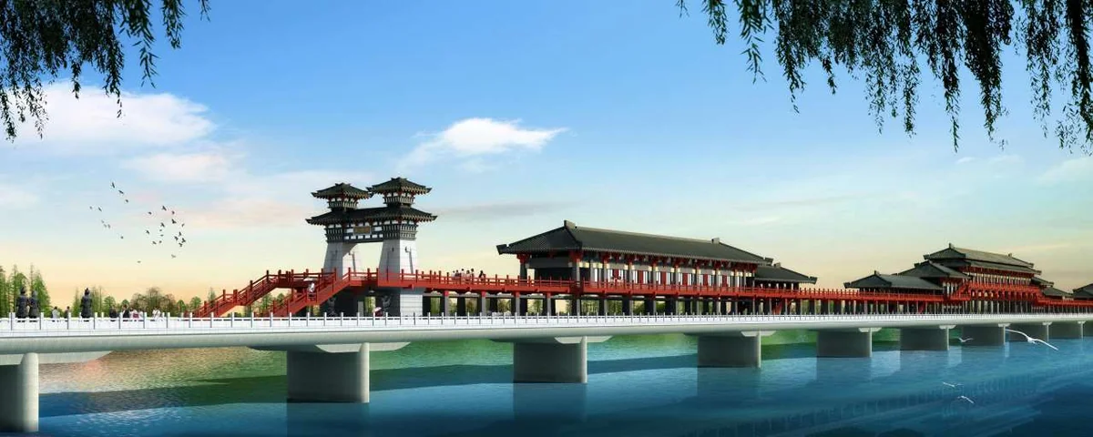
This guide is written for owners, engineers and contractors involved in steel bridge tenders and reviews. It follows EN 1993-2 (Design of Steel Structures — Steel Bridges) with EN 1993-1-9 for fatigue, AASHTO LRFD Bridge Design Specifications for North American projects, and the Chinese railway bridge design code (TB 10002 series) where railway loading governs. The reference case is the 748 m Xianyang Covered Bridge across the Weihe River in Shaanxi — one of the longest covered bridges in China — whose steel structure we fabricated and erected, which is why this article treats large landmark spans and practical bridge engineering as the same discipline.
We cover system selection, deck systems, bearings and expansion joints, fatigue, corrosion protection, and the construction methods that decide so much of the design.
1. System Selection: Girder, Truss, Arch and Suspension
The bridge system is chosen from span, clearance, loading, aesthetics and construction access, in that order. Each system has an economical domain, and choosing outside it is the most expensive mistake a bridge owner can make.
| System | Economical span | Typical deck | Governing issue |
|---|---|---|---|
| Plate / box girder | 30 – 80 m | Composite RC slab or orthotropic | Deflection, deck cracking |
| Truss | 60 – 150 m | Orthotropic or RC slab | Joint fatigue, bracing |
| Arch / tied arch | 80 – 300 m | Composite or orthotropic | Rise and clearance, buckling |
| Suspension / cable-stayed | 200 m and above | Orthotropic (long spans) | Aeroelasticity, cable fatigue |
For the common mid-span range (50–150 m), a steel-concrete composite box or plate girder competes with a steel truss; the girder is faster to fabricate and paint, the truss is lighter for given depth and suits rail loading. The covered-bridge and landmark segment — where the structure is partly building and partly bridge — sits between these, and it is where our Xianyang bridge experience applies: a 748 m continuous structure whose multi-span steel frame carries pedestrian and light-vehicle loads across a major river while supporting a fully enclosed deck building above.
2. Deck Systems: Orthotropic Steel Plates
For spans beyond about 100 m and for every long-span bridge, the self-weight of the deck dominates the economics, and the answer is the orthotropic steel plate deck: a thin deck plate stiffened in two directions by longitudinal ribs (usually closed U-ribs) and transverse floor beams, so that the deck plate itself carries traffic loads directly into the rib system. Typical proportions are a deck plate of 14–16 mm, U-ribs 280–300 mm deep with 6–8 mm walls at 320–600 mm centres, and floor beams at 3–4 m spacing.
Orthotropic decks are supremely efficient and famously demanding at one point: the rib-to-deck weld. It is partially penetrated, loaded by every wheel passage, and subjected to the highest stress concentration in the bridge. Three rules govern it: the deck plate is never thinner than 14 mm where tyres run, the rib-to-deck joint is executed with the root side verified, and the weld toe is positioned and ground to remove the worst notch. The lesson that drops from every orthotropic deck failure in the record: never let the deck plate thickness, the rib spacing or the weld detail be value-engineered downward — they are fatigue details first, steel second.
3. Bearings and Expansion Joints
A bridge moves. Thermal movement at α = 12 × 10-6 /°C over a 100 m structure with a 70°C annual swing is 84 mm, before creep and shrinkage of the concrete deck are added. The bearing system must accommodate that movement, transmit the vertical reactions, and still guide the deck under wind and braking: pot bearings or spherical bearings, with guide keys providing longitudinal restraint where the structural system requires it, and elastomeric pads where rotations dominate. The expansion joint, in turn, must seal that movement against water and road salts — the single most maintenance-intensive component of a steel bridge deck.
Design practice for engineers and owners: specify the joint travel class explicitly (e.g., 120 mm class for the 100 m span above), require the deck drainage to pass the joint without wetting the steel below, and put the bearing replacement procedure in the Owner’s Manual at design stage — bearings are replaceable components, and the lifting points and jacking layout should already be in the drawings.
Bearing Types at a Glance
Three bearing families cover nearly every steel bridge. Elastomeric bearings (plain or with steel laminates) allow rotation and modest translation with zero maintenance, and suit spans to about 40 m. Pot bearings separate vertical load and rotation: a cylindrical pot with a confined elastomer disk carries the vertical load while the rim absorbs rotation, and adds guided translation via PTFE sliding shear keys. Spherical bearings do the same with a spherical steel interface, carrying higher rotations and larger loads with compact overall height — the usual choice for the 100 m class and above. The selection table in the design report should state, for each pier: vertical reaction, longitudinal and transverse movement range, rotation demand, and the maintenance access position, because a bearing without an inspection and replacement plan is a future bridge closure.
4. Fatigue Design: S-N Curves and Detail Categories
Fatigue is where bridge design separates from building design. A road bridge sees on the order of 2 × 10⁶ design cycles over 100 years; a rail bridge accumulates several times that with heavier axles. Steel never fails in fatigue by average stress — it fails at the stress range of the worst detail, so the design effort goes into classifying every weld detail and keeping its stress range below the S-N curve of its category. EN 1993-1-9 assigns detail categories from 36 to 160 MPa at 2 × 10⁶ cycles; AASHTO works with constant-amplitude fatigue thresholds (CAFT) on the same principle.
| Detail | EN 1993-1-9 category (MPa) | Δσ at 2 × 10⁶ cycles | Typical location |
|---|---|---|---|
| Butt weld, ground flush | 125 – 160 | 125 – 160 MPa | Flange splices, deck plate welds |
| Butt weld, as welded | 90 | 90 MPa | Web splices |
| Fillet weld toe, end plate | 71 | 71 MPa | Gusset toes, stiffener ends |
| Long attachment, free end | 50 | 50 MPa | Longitudinal stiffener terminations |
The manufacturing translation of fatigue design is detail discipline: grind butt weld caps flush in tension zones, terminate stiffeners with run-out tapers, keep attachments off tension flanges, and control weld profile at every toe. The design translation is the budget: if the governing detail class is 71 MPa, the allowable stress range is 71 × (2 × 106/N)1/3 for a different cycle count — and doubling the cycles of the design reduces the allowable range by 26%, which is why rail and heavy-traffic bridges demand lighter utilisation before they demand more steel.
Applying the S-N Calculation
The fatigue check is applied as a stress range budget, not a strength check against peak stress. For a detail in category 71 MPa at the reference 2 × 10⁶ cycles, the allowable stress range at any other cycle count N follows the inverse slope of the S-N curve (m = 3 in EN 1993-1-9):
ΔσR = 71 × (2 × 106 / N)1/3 → at N = 10 × 106 cycles: ΔσR ≈ 41 MPa
The same detail that passes comfortably at road-bridge cycles (2 × 10⁶) becomes the governing member condition at rail cycles (10 × 106 and beyond), which is why heavy-traffic and rail bridges are detailed with category 100+ details in the deck region and why the cycle count, not the span or the tonnage, should open every fatigue review conversation.
Fatigue Detailing Rules That Are Non-Negotiable
- Terminate stiffeners and gussets with run-out tapers (typical 1:3 on the flange direction) so the weld toe is never a stress concentration at a section change.
- Keep attachments off tension flanges; where unavoidable, the attachment length and end detail are engineered, not sketched.
- Butt weld caps in the tension zone are ground flush and transitioned, and the grinding direction follows the stress flow.
- Bolted splices in fatigue-critical zones are slip-critical, with the hole pattern verified for net-section fatigue of the splice plates.
5. Heavy Anti-Corrosion Systems: ISO 12944 C5
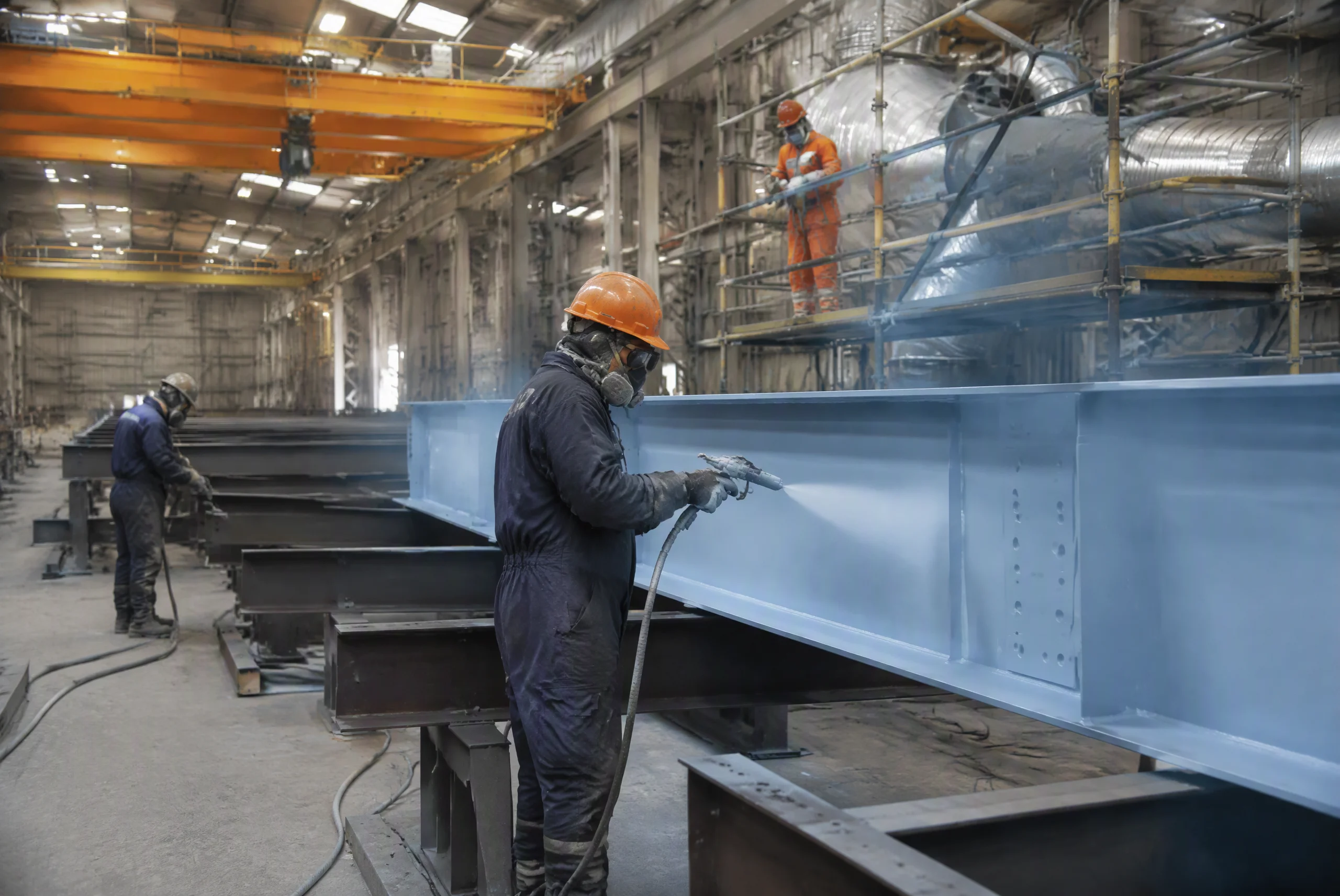
Bridge steel corrodes from two directions: the atmosphere from outside and the deck drainage from above. ISO 12944 classifies bridge environments as C4 to C5 (often C5-M for marine and de-icing-salt exposure), and the standard heavy system for a road bridge is a three-coat scheme: inorganic zinc-rich primer 75 μm, epoxy micaceous iron oxide (MIO) midcoat 125 μm, and aliphatic polyurethane topcoat 50 μm, for a total dry film thickness of 250–320 μm, with high-build or duplex systems where splash zones and salt exposure demand more. Every flange crevice, bolted splice and welded hollow section interior gets the same coating reach as the visible surface — the corrosion that kills bridges starts where paint could not reach.
Whole-life thinking decides the difference between a good and a poor bridge specification. The owner should require a coating maintenance plan with defined inspection intervals (typically 6–12 years to first maintenance for C5), touch-up procedures, and access provisions (walkways, inspection gantries) designed into the structure at tender stage. A steel bridge whose maintenance is impossible to reach is a steel bridge with a predetermined lifespan.
Coating Repair and Field Touch-Up
No bridge coating survives its erection untouched: sling marks, welding repairs, bolt tightening and transport abrasion all open the paint film, and each opening is a corrosion cell. The specification must therefore include the field touch-up protocol with the same materials as the shop system: abrade the damaged zone, feather the edges, apply the full three-coat sequence locally, and verify dry film thickness with the same DFT gauge used in the shop. Two details separate a durable scheme from a decorative one: full DFT and adhesion testing on 5% of repaired areas, and the repair of all bolts and fittings after torqueing, because the zinc-rich primer on fasteners is the first point where salt water finds the steel.
6. Construction Methods: Launching, Cantilever and Integral Lifting
Bridge erection over traffic is the classic constraint, and it converts the method into design loads. Three methods dominate.
- Incremental launching: the steel superstructure is assembled on the bank, complete with a launching nose, and progressively pushed across the piers on sliding bearings. The design must include the launching forces, the sagging moments of the cantilever tip at each push step, and the temporary load cases — often the launching case, not the service case, sizes a mid-span girder.
- Cantilever erection: segments are lifted and connected at the advancing tip, with the completed span balanced by tie-downs or counterweight. The method suits spans over rivers and gorges where falsework is impossible; its design consequence is a stack of erection joints whose fit-up tolerance must be controlled at millimetre level.
- Integral lifting: for arch ribs, large single components or whole sub-assemblies, strand jacks lift weights of hundreds to thousands of tonnes from ground-level assembly areas. The design must include the lifting lug geometry, the jacking load cases, and the synchronous jacking controls — the failure mode to design against is differential lift, not lifting capacity.
The owner should never see "erection loads within the design envelope" as an afterthought sentence: the bridge design documents should list the governing erection load case for each member, because on a launched bridge the launching nose and sliding shoes are structural members with the same drawings as the permanent works.
7. Reference Case: the 748 m Xianyang Covered Bridge
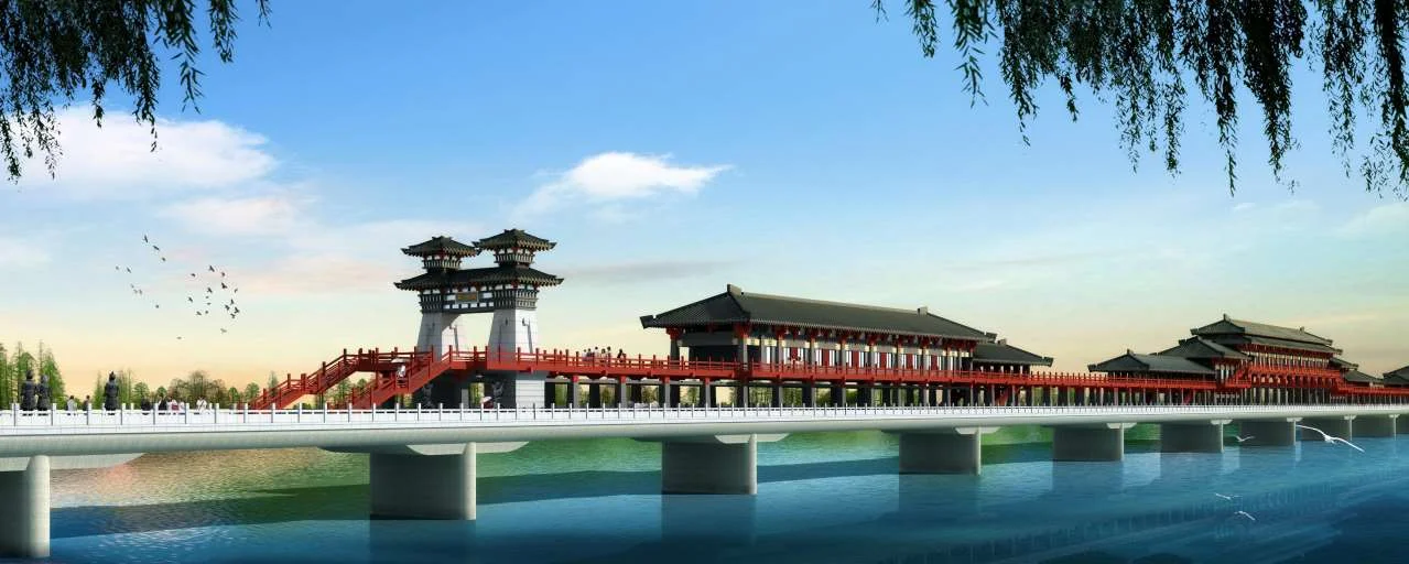
The Xianyang Covered Bridge spans the Weihe River in Shaanxi Province with a total length of 748 m, making it one of the longest covered bridges in China. Its steel structure carries a fully enclosed two-level deck — pedestrian corridor below, sheltered observation spaces above — across multiple river piers, combining the behaviour of a continuous multi-span bridge with the dead and wind load of a building envelope on top. Our scope covered the fabrication and erection of the steel structure, including the shop fabrication of the deck and enclosure steelwork, the corrosion protection system, and the erection sequence coordinated with river conditions and wind exposure at the site. It is a demonstration that bridge design essentials — movement, fatigue, corrosion, erection — apply with full force to covered and landmark bridges, and that the same discipline serves a 30 m pedestrian underpass and a 748 m river crossing.
Key Takeaways
- System follows span, loading and access: girders to 80 m, trusses to 150 m, arches to 300 m, cable-supported above — with clearance and construction access as co-equal inputs.
- Orthotropic decks win on weight and live by fatigue detail: deck plate ≥ 14 mm, U-ribs 6–8 mm at 320–600 mm centres, and the rib-to-deck weld never value-engineered downward.
- Movement is designed, not estimated: αLΔT calculations set the bearing travel class and expansion joint class, with replacement procedure drawn at design stage.
- Fatigue governs steel bridges: classify every weld detail per EN 1993-1-9 (36–160 MPa categories) or AASHTO CAFT, and budget allowable stress ranges against real cycle counts, not nominal ones.
- Corrosion protection is a whole-life system: ISO 12944 C5 three-coat schemes at 250–320 μm DFT, with maintenance access and repainting plan in the tender documents.
- The erection method is a design input: launching, cantilever and integral lifting each add member-level load cases that must appear in the drawings.
For a steel bridge — from a 30 m footbridge to a landmark river crossing — our engineering team provides system selection, fatigue and corrosion specifications, fabrication and erection support, with references from the 748 m Xianyang Covered Bridge. Contact our engineering team for a bridge feasibility study or fabrication enquiry.
Need a Steel Bridge Engineered, Fabricated and Erected to EN, AASHTO or Chinese Practice?
With the 748 m Xianyang Covered Bridge among our references, we deliver steel bridges with fatigue and corrosion engineering documented, and erection sequences planned for traffic-free operation. Send us your alignment, span and loading for a preliminary assessment.
Request a Consultation