
Large-Span Steel Structure Erection Methods: Choosing the Right Approach
For a large-span steel roof or bridge, the erection method is often the most consequential decision in the project — more than the member sizes, because it dictates the cranes, the temporary works, the schedule, and the risk profile. A 100-meter roof truss can be assembled on the ground and lifted whole, erected as blocks by a heavy crawler crane, or pushed across the site by hydraulic jacks. Each method is valid; each is correct for a different set of site conditions, and choosing wrongly can add months and substantial cost.
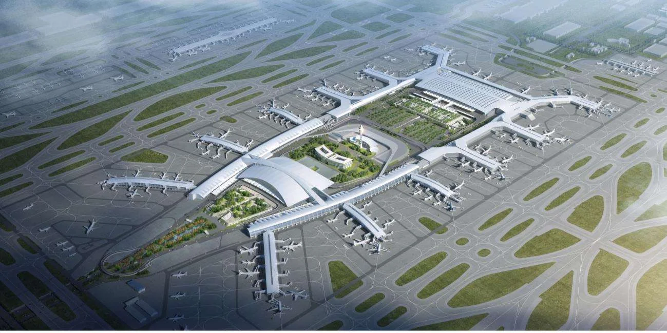
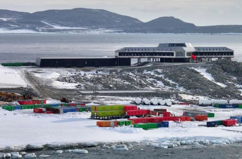
This guide compares the principal erection methods used for large-span steel structures — spatial grids, pipe trusses, portal frames, and bridges — and explains the engineering criteria that govern the choice: available crane capacity, site access, height above ground, wind exposure, construction window, and tolerance control. The examples referenced are public projects we fabricated or supplied, including the Antarctic Ross Sea Station with its 60-day construction window and the Guangzhou Baiyun International Airport Phase III Expansion roof, erected with large-scale integral lifting.

1. Ground Assembly with Integral Lifting
In integral lifting (also called integral hoisting or the "ground assembly, integral lifting" method), the entire roof or a major section of it is assembled at ground level on temporary supports, then raised into its final position using synchronized hydraulic jacks or strand jacks. The Guangzhou Baiyun International Airport Phase III roof is a landmark example of this approach on a very large scale: a massive steel roof deck assembled on the ground and lifted by a synchronized jacking system, which dramatically reduced the required crane capacity and improved welding and assembly quality at ground level.
The method works when the ground around the building can accommodate temporary assembly beds. Its advantages are decisive in the right conditions:
- Quality: the majority of welding and bolting is done at ground level where access, inspection, and quality control are straightforward.
- Crane demand: lifting a completed structure requires fewer lifting points than a crane of comparable capacity — synchronized jacks share the load across 8–40 lifting points.
- Safety: erectors spend far less time working at height on loose members.
The engineering content is the lifting system itself: lifting point layout must keep the deformation of the structure within elastic limits during lifting (typically deflection controls around L/400 to L/500 for sensitive grids), the jacking system must be synchronized within a few millimeters between points, and the temporary lifting towers and anchors must be designed for the lifted weight plus dynamic factors. Lifting at a rate of 2–5 m per hour for a multi-thousand-tonne roof is routine; the method's limit is site layout — if the building sits among existing structures with no ground assembly zone, other methods take over.
2. Block Erection by Crane
Block (or unit) erection divides the roof or frame into pre-assembled blocks, each weighing several tonnes to hundreds of tonnes, which are then lifted into position by mobile or crawler cranes. This is the standard approach for industrial buildings, convention centers, and stadium roof segments with spans up to roughly 60–80 m.
| Structure type | Typical block weight | Typical crane capacity | Governing criterion |
|---|---|---|---|
| Portal frame, 30–40 m span | 2–8 t | 50–100 t mobile crane | Lift radius and boom length |
| Grid roof, 40–80 m span | 15–60 t | 150–300 t crawler crane | Block stiffness during lift |
| Truss or arch, 80–120 m span | 60–200 t | 400–800 t crawler/gantry | Lifting lug capacity; stability |
The crane selection calculation is not simply "block weight plus slings". The governing number is the product of load, radius, and boom height: a 40 t block lifted at a 30 m radius by an 80 m boom demands a machine far larger than the payload alone suggests — typically 250–400 t class. Every block erection plan should include a lift study tabulating weight, center of gravity, rigging, radius, and utilization per crane configuration, reviewed for wind and for the structure's own stiffness under its self-weight in the lifted configuration.
3. Cumulative Sliding and Incremental Launching
Hydraulic sliding (also called cumulative sliding or incremental launching) assembles the structure at one end of the site on a fixed assembly bed and progressively slides or launches it toward the final position. The method has moved roofs of more than 200 m and bridges of 500 m or more. The Guangzhou Baiyun airport roof and many long-span station roofs have used variants of this technique where erecting in place was impossible over operating areas.
The operating principle: the structure is assembled in sections, each section is pushed forward on Teflon-stainless steel slide bearings or roller systems, and the next section is assembled behind it — hence "cumulative". For roof structures, the assembly bed sits on the ground or on temporary towers; for bridges, the launching nose guides the deck onto piers. Friction is overcome by hydraulic jacks acting on the structure or by strand-jack pulling systems, with computers synchronizing multiple jacks to avoid skew.
Sliding has three engineering constraints that need specialist attention:
- Tribology: Teflon-on-stainless coefficients of friction run 0.05–0.12 static and 0.03–0.06 dynamic; the plan must size jacks for the worst combination and provide for re-lubrication.
- Stability during slide: the structure must be braced against lateral buckling and against wind during the slide, when it is supported at far fewer points than in service.
- Alignment tolerance: sliding 200 m while staying within millimeters requires guide rails, survey control, and correction jacks at the supports.
Roof sliding is at its most valuable when the building footprint is already occupied — for example, erecting a terminal roof over an operating railway station or airport area. The trade-off is the cost of the assembly bed and the sliding equipment, which is economic only for longer spans or inaccessible site portions.
4. Cantilever Erection for Bridges
Cantilever erection builds a steel bridge out from each pier toward mid-span, with the erected portion acting as a temporary cantilever until the segments meet. It removes the need for falsework spanning the water, valley, or traffic below — which is why it dominates for long steel bridges and for crossings above live railways and highways.
Each segment is lifted by a derrick or crane mounted on the completed portion, connected, and the cantilever advanced. Because a cantilever can only reach approximately 1.5–2.0 times its own dead-load capacity before overturning, temporary stay systems or counterweight arrangements are used for very long spans. The method demands meticulous control of erection geometry: because deflection accumulates with each segment, the preset or "erection camber" must be computed and measured at every stage, and closure gaps at mid-span are typically closed using a jacking or forced-displacement procedure to set the final profile.
For steel bridges, bolted high-strength connections are preferred at assembly joints, allowing disassembly for transport and rapid field work. The same philosophy — bolted, modular, erection-friendly design — applies to the steel bridges we fabricate across the industry.
5. High-Altitude Loose Assembly vs. Unit Installation
When ground assembly is impossible — for example, an interior roof bay above an operating plant — engineers fall back to in-place assembly at height. The two variants differ in how much work happens in the air:
| Criterion | High-altitude loose assembly | Unit (block) installation | Effect on project |
|---|---|---|---|
| On-site work at height | High — every joint made in the air | Low — joints closed on lifted blocks | Hours of work and safety exposure |
| Crane requirement | Smaller lifts, many of them | Fewer, heavier lifts | Equipment cost and site layout |
| Shop welding vs field welding | More field bolts; often field welding | Welding concentrated in factory blocks | Quality consistency and productivity |
| Typical span range | Any, but favored for complex grids | 30–90 m roof and frame structures | Schedule and cost envelope |
The industry trend is unmistakable: unitization. Factory-welded, pre-assembled blocks reduce field welding, cut schedule, and improve quality — but they demand that the design, fabrication, and erection teams coordinate tolerances from the first drawing, because a block that does not fit costs far more to correct than a loose member.
6. Erection Tolerances and Quality Control
Erection tolerances are not preferences — they are engineered values tied to the design. Common acceptance criteria for large-span steel structures (per Chinese code GB 50205 and aligned with EN 1090 practice):
- Column verticality: H/1000, with an absolute limit of typically 25 mm for columns up to 25 m; for taller columns, the limit scales proportionally.
- Beam and truss levelness: deflection relative to design profile within L/1000 or a 10–15 mm absolute band for truss chord lines, whichever governs.
- Grid node positions: plan position of grid nodes within ±5 mm at supports and ±L/2000 elsewhere in many specifications.
- Bolted connection fit: joint gaps within 0.5–1.0 mm for slip-critical connections, driving the need for pre-assembly in the factory.
- Total building lean: the peak displacement of the completed frame within 0.1% of height (H/1000) for most codes.
The practical consequence: tolerances accumulate. A structure built from three blocks each out of plane by 5 mm can miss its envelope by 15 mm even though every block "passed". This is why we pre-assemble large spans in the workshop with full trial bolting, mark the control lines, and ship the survey data to site. Pre-assembly is not decoration; it is the only reliable way to guarantee field fit for members fabricated under different cutting batches.
7. Safety and Lifting Calculations
Erection safety is engineered, not administered. The governing inputs for a lifting plan are:
- Load verification: the lifted weight must include the structure itself, rigging (slings, spreaders, shackles), and any attachments — commonly adding 5–15% to the bare weight.
- Dynamic and impact factors: codes apply a dynamic amplification factor (typically 1.1–1.3) to account for acceleration during pick-up and set-down; a "1.25 × weight" check is common.
- Wind limits: most lifting procedures cap wind at 10–12 m/s at hook height; large flat roofs are lifted at far lower limits (some at 6 m/s) because their sail area dominates.
- Rigging design: sling angles below 60° from horizontal multiply tension — a 30° sling angle doubles the sling load — which is why spreader beams are mandatory for wide lifts.
- Ground bearing: crane outrigger pressure at the furthest radius determines matting requirements; a 400 t crane at full radius can exceed 500 kPa on the ground, demanding engineered cribbing.
The Antarctic Ross Sea Station demonstrates the extreme case: a 60-day weather window in which the entire steel frame had to be erected, with no possibility of redo for several months. The design eliminated field welding entirely, using bolted modules that fit within strict tolerances established by factory pre-assembly — erection strategy decided at the design stage, not on site. That is the principle for every project described in this guide.
Key Takeaways
- Ground assembly with integral lifting wins on quality and schedule when the site has space for an assembly bed — synchronized jacks share the load and minimize working at height.
- Block erection is the workhorse for industrial and roof structures; the crane decision is driven by load × radius × boom height, not payload alone.
- Cumulative sliding and launching move structures over occupied sites — roofs beyond 200 m and bridges far longer are routinely built this way.
- Unitization beats loose assembly for quality and speed, but only when tolerances are coordinated from design through fabrication to site.
- Erection tolerances (H/1000 verticality, mm-level grid positions) are engineered values, and factory pre-assembly is the only reliable guarantee of field fit.
Choosing an erection method is a design decision and a cost decision. Send us your structure type, span, site constraints, and available crane fleet, and our engineering team will recommend an erection methodology with a lifting scheme and schedule. Contact our erection engineering team or browse our project portfolio for examples of each method in service.
Erection Engineering for Any Span, Any Site
From factory pre-assembly to synchronized lifting and sliding, we engineer the erection method into the design so your schedule and budget survive contact with the site. Share your structure details for a method recommendation.
Discuss Your Erection Plan