
Steel Structure Fabrication Process: From Detailing to Pre-Assembly
Between an approved structural design and steel standing in the air lies the fabrication process — a chain of workshops, machines and inspectors that converts design intent into geometry with millimetre tolerance. A 20,000-tonne project, which in the spatial grid and pipe truss sector is a large coal shed, airport roof or exhibition centre, moves through this chain roughly as 800-1,200 individual members, 40,000-60,000 shop welds and 200,000+ bolt holes. Every one of those welds and holes is governed by an acceptance level, and every primary member carries a traceability mark back to a specific plate cast.
Fabrication quality is not an add-on; it is the entire product. A truss chord that arrives 8 mm out of camber cannot be forced into position without re-introducing locked-in stress, and a bolted sphere joint with damaged threads stops an entire bay of an erection schedule. This article walks through the seven stages of fabrication for large steel structures — detailing, material procurement, cutting, assembly and welding, straightening and blasting, coating, and pre-assembly — with the real parameters our shop controls at each stage, and closes with a typical schedule for a 20,000-tonne programme.
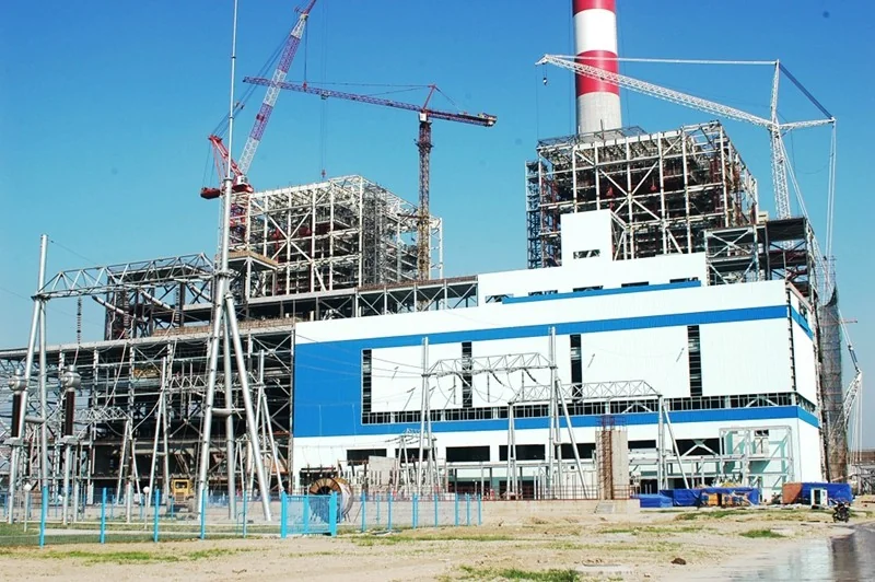
1. Detail Design and Shop Drawings (Tekla / SDS2)
Fabrication starts from detail design — the translation of the engineer’s design into era-plus-member shop drawings. We model the complete structure in Tekla Structures (and SDS2 for US-standard projects), which generates three outputs simultaneously: erection drawings for the site, single-part and assembly drawings for the shop, and CNC data files (DSTV format) that drive the cutting machines directly from the model.
At this stage the discipline is geometric, not creative:
- Member marking: every member receives a unique mark referenced in the erection sequence; the mark is transferred to steel during fabrication and appears on every drawing and packing list.
- Weld symbol allocation: joint classification (butt, fillet, partial penetration), weld size, length and position per ISO 2553 are fixed in the model, so the shop never decides weld size by habit.
- Clash and tolerance review: the model is checked against the bolt clearances, end-plate fits and coating access; on long-span trusses we add trial camber values to the geometry so the finished member deforms up to the theoretical profile.
- Material optimisation: nesting software groups identical parts to raise plate utilisation from a typical 75-80% to 85-90%, which on 20,000 tonnes is 1,000-2,000 tonnes of plate saved — the single biggest cost lever in the process.
2. Material Procurement and Receiving Inspection
Plate and section steel arrives with mill certificates stating the heat number, chemical composition and mechanical properties per GB/T 17505 or EN 10204 3.1. Receiving inspection verifies four things: grade and dimensions against the purchase order; chemical composition limits (for Q355, carbon ≤ 0.24%, phosphorus and sulphur ≤ 0.030% typically); mechanical properties (yield, tensile, elongation, Charpy impact); and for plates 40 mm and thicker, ultrasonic testing of the full plate area to GB/T 2970 to detect internal laminations before cutting.
Two parameters matter for weldability and are checked heat by heat: the carbon equivalent and the weld cracking parameter. For Q355 plate we hold Ceq = C + Mn/6 + (Cr + Mo + V)/5 + (Ni + Cu)/15 at or below 0.44, which keeps preheat requirements and cold-cracking risk manageable. The accepted heat numbers are stencilled onto the plate stock, and from that moment every cut part carries its traceability mark — this is the same discipline that EN 1090-2 execution classes require, and it is the cheapest insurance policy in the entire programme.
3. Cutting and Edge Preparation
Cutting technology is selected by thickness and edge quality requirement:
- CNC oxy-fuel cutting for plates thicker than 30 mm, including the 40-80 mm flange plates of heavy columns and truss chords; edge quality up to ISO 9013 range 2, with kerf compensation applied from the DSTV data.
- CNC plasma cutting for the 6-30 mm range at high speed — the workhorse for web plates, gussets and node plates.
- Laser cutting for parts up to 20-25 mm where edge squareness and hole quality are critical (end plates, base plates, cleats), eliminating secondary drilling for most holes below 30 mm.
- Beveling and joint preparation: full-penetration butt joints are beveled (typically single-V 45° at 60-90° included angle for t ≤ 40 mm, double-V for thicker sections) to achieve the root gap and weld metal volume the WPS is qualified for.
Thermal distortion is controlled at the source: cutting is sequenced so heat input balances across the part, and large plates are cut with skeleton retention tabs so the part stays in the plate until final separation. For 100+ metre truss chords, sections are cut long by the predicted weld shrinkage and camber allowance, then trimmed in assembly.
4. Assembly and Welding
Assembly brings cut parts together into sub-assemblies (nodes, joint clusters, chord segments) and then into full members. Fit-up tolerances are controlled to GB 50205 / EN 1090-2 Class 2: root gaps within ±2 mm, offset within 10% of the thinner plate, and part alignment verified before any weld is deposited.
Welding process selection follows joint and position:
- Submerged arc welding (SAW) for long straight butt welds and fillet welds in the flat position — box columns, H-beam flange-to-web welds, chord splices. Typical parameters for 20-40 mm plate: 550-700 A, 30-36 V, travel speed 25-45 cm/min, single or twin wire with bonded flux (e.g. S101 / F4A2-EM12K type), heat input controlled to keep HAZ toughness per the WPS.
- Gas metal arc welding (GMAW/CO2) and FCAW for positional welds — nodes, diaphragms, stiffeners — with 1.2 mm solid or cored wire at 250-320 A, 28-32 V.
- Preheat and interpass control: per GB 50661, preheat of 60-80°C is typical for Q355 in thicknesses above 30 mm; interpass never drops below preheat and never exceeds 250°C. Temperature is verified at 75 mm from the joint centreline with contact pyrometer or temperature crayons.
- Back-gouging: full-penetration joints are air-carbon-arc gouged to sound metal on the root side, ground to bright metal, examined, then sealed with a second pass sequence.
Welding sequence is engineered, not improvised: on long box columns we alternate passes about the neutral axis and use balanced one-sided welding in alternating bays to hold longitudinal shrinkage and camber within tolerance. On space frames, welds at each node are deposited in a specified order and the node is allowed to cool between passes to limit cumulative distortion.
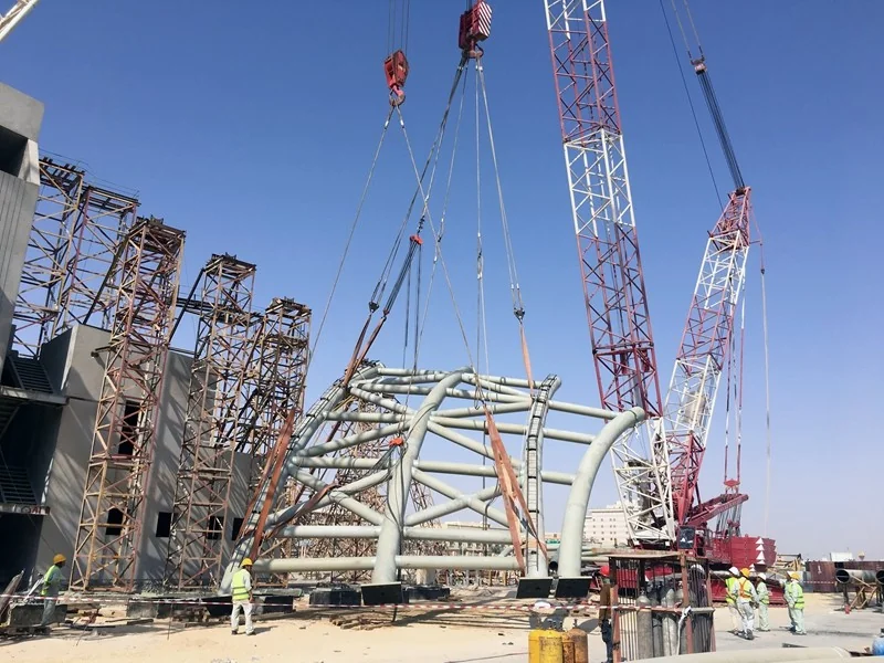
5. Straightening, Shot Blasting and Surface Preparation
Weld shrinkage inevitably pulls geometry. Members are checked on levelling beds against the millimetre offsets in the drawings, and corrected by flame straightening (localised heating to 600-800°C in controlled patterns — never above 900°C, which damages the microstructure of Q355) and mechanical press correction for angular misalignment. Straightening to tolerance before painting is mandatory: a coating cannot hide a member that is out of plumb by 12 mm.
Surface preparation then proceeds in one pass:
- Shot blasting to Sa2.5 (ISO 8501-1): the surface is cleaned of mill scale, rust and contamination to a “near-white metal” finish — the default specification for structural steel before painting. Abrasive is steel shot/grit mix, recycled through a magnetic separator to control dust loading.
- Surface roughness profile is kept in the medium G band of ISO 8503-1 (40-70 μm) — deep enough to key the primer, shallow enough to avoid peaks starved of paint coverage.
- Cleanliness checks: dust rating to ISO 8502-3 (rating 2 or better on painted surfaces in aggressive environments) and salt-contamination checks where the project specifies them, especially for coastal coating specifications.
6. Coating Application
Coating systems for structural steel follow ISO 12944 categories. A typical C4 (industrial/coastal, high corrosivity) specification used on large grid and truss projects is a three-coat system:
- Primer: inorganic zinc-rich, 70-80 μm dry film thickness (DFT) — sacrificial anode protection at the substrate.
- Intermediate: epoxy micaceous iron oxide (MIO), 120-160 μm DFT — the barrier layer that blocks water and chloride.
- Topcoat: aliphatic polyurethane, 50-60 μm DFT — UV stability and colour retention.
- System totals: 260-300 μm DFT, measured per ISO 19840 at the specified points (typically 80-90% of points within tolerance band, none below minimum).
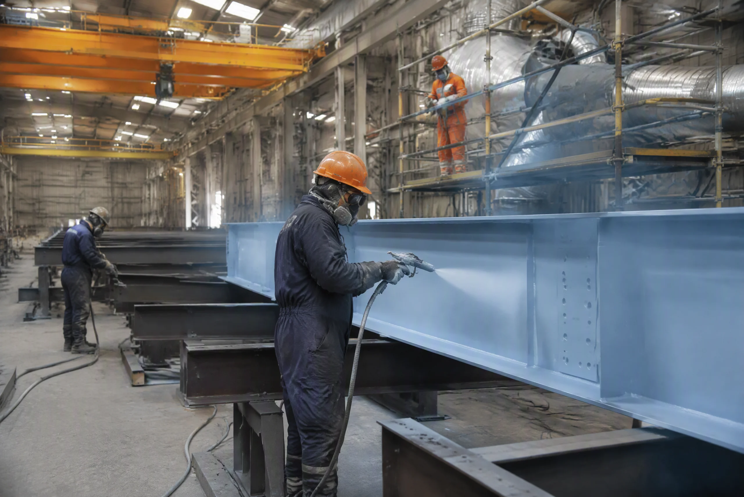
Application conditions are enforced, not suggested: ambient relative humidity below 85%, steel temperature at least 3°C above the dew point, and wet-film checks every shift. Airless spray at 200-250 bar achieves transfer efficiency above 65%, and weld areas, edges and cut-outs receive a stripe coat before the full film. For members that will be bolted on site, friction surfaces are masked before blasting and painting to preserve the specified slip factor — our coating and finishing services cover the galvanizing-versus-painting decision, System DFT targets and friction-surface masking in detail.
7. Trial Assembly, Final QC and Release
For long-span and spatial structures, trial (pre-)assembly is where geometry risk is retired. We assemble representative bays — typically the first grid module, a full truss panel or the joint clusters around the highest-loaded nodes — on the shop floor to verify:
- bolt hole alignment and group fit (100% of holes accept bolts freely in the trial bay);
- global dimensions against the theoretical model, including camber and pre-set values;
- member marks, orientation and erection sequence logic before anything is shipped;
- access for erection crews and lifting points for the site crane plan.
Final QC bundles the documents a contractor actually needs: NDT reports (ultrasonic, magnetic particle, radiographic per the ITP), coating DFT records, straightness and dimension reports, material certificates with heat numbers, weld procedures and welder registers, and the packing list with member-by-member marks and weights. Only then is the batch released for packing and shipping.
Typical Schedule for a 20,000-Tonne Programme
The schedule below reflects a dedicated fabrication plant running three assembly lines, with stages overlapping where the critical path allows. It is typical for a large grid roof or storage building programme:
| Stage | Typical duration (weeks) | Key activities and milestones |
|---|---|---|
| Detail design & shop drawings | 8-10 | Tekla model, member marking, CNC data release; first-bay drawings for material ordering |
| Material procurement & receiving | 6-8 (overlaps detailing) | Mill orders, 3.1 certificates, UT on thick plate, heat-number tagging |
| Cutting & part production | 6-8 | CNC oxy-fuel / plasma / laser parts, beveling, nesting for utilisation ≥ 85% |
| Assembly & welding | 26-32 | Node clusters, chord segments, box columns; SAW/GMAW; preheat control; at ~600-750 t/month per line |
| NDT & repair | 4-6 (parallel with welding) | UT/MT per ITP, repairs, re-test; issuance of weld records |
| Straightening, blasting & coating | 8-10 | Flame/press straightening, Sa2.5 blasting, DFT-controlled coating, curing |
| Trial assembly & final QC | 4-6 | Bay assembly, dimension reports, third-party witness, document pack |
| Packing, shipping & documentation | 3-4 | Member-by-member packing lists, marks, weights; sea/road freight coordination |
With realistic overlap, a well-run 20,000-tonne programme fits in roughly 44-52 weeks from drawing release to final shipment. The rate-limiting step is almost always welding capacity — which is why committed programmes reserve machine capacity, not just plate, before fabrication starts.
Key Takeaways
- Detailing is where the geometry is won or lost. Tekla/SDS2 modelling feeds CNC cutting directly and fixes member marks, weld sizes and trial camber before any steel is ordered.
- Traceability starts at receiving. Heat-number tagging, composition checks and Ceq control (target ≤ 0.44 for Q355) are the foundation of weldability and of any EN 1090-2 or project-specific audit.
- Welding parameters are engineered, not improvised: SAW at 550-700 A / 30-36 V, preheat 60-80°C above 30 mm, interpass cap 250°C, and sequenced passes to control distortion.
- Coating is a system, not a paint job: Sa2.5 preparation, 40-70 μm roughness profile, zinc-rich + epoxy MIO + polyurethane at 260-300 μm DFT for C4 environments, with environmental conditions enforced.
- Trial assembly retires erection risk. A representative bay verified for bolt fit and global geometry is worth more than any document pack — and the document pack (NDT, DFT, certificates, packing lists) is what releases the batch.
Every stage above is performed under documented quality systems in our Xuzhou plants, with third-party inspection accommodated at every hold point. If you are planning a large steel structure programme and need a fabrication partner, contact our engineering team with your drawings and programme dates — we will confirm feasibility, capacity and a stage-by-stage schedule within 24 hours.
Planning a Large-Scale Steel Fabrication Programme?
Share your tonnage, member types and schedule. Our team will match capacity, confirm the stage-by-stage plan and return a fabrication quotation with milestone commitments within 24 hours.
Request a Fabrication Quotation