
Steel Structure Foundation Design: Base Plates, Anchors and the Load Path
Every steel structure ends the same way: as a series of concentrated column reactions arriving at a foundation that spreads them into the ground. It sounds trivial, yet foundation problems generate some of the most expensive claims in steel construction — anchor bolts that do not fit the erected columns, bases that rock under wind uplift, and differential settlement that tilts crane rails or cracks partitions. Most of these are not geotechnical failures; they are interface failures, caused by the steel designer and the foundation designer working on different drawings with different assumptions.
This guide is written for project owners, engineers and general contractors who need to review or specify the concrete side of a steel-framed building: foundation system selection, base plate and anchor bolt design, the investigation data that feeds them, and the settlement limits that protect the steel above. It follows GB 50007-2011 (Code for Design of Building Foundation) and GB 50010 for the concrete, GB 50017-2017 for the steel connection, and cross-references AISC Design Guide 1 (Base Plate and Anchor Rod Design) and Eurocode practice where projects are tendered internationally.
We treat the steel-to-foundation connection as one continuous load path, because that is how it actually behaves, and that is how it should be designed, detailed and checked.

1. Foundation System Selection
Four families cover steel building foundations, and the selection logic is driven by column load, soil bearing pressure and settlement, in that order. Table below summarises the guidance; the paragraphs after explain the load path that makes the steel interface work.
| Foundation type | Typical application | Soil condition driver | Governing issue |
|---|---|---|---|
| Isolated pad (independent footing) | Light frames, column loads ≤ 3,000 kN, grid supports | Competent soil at shallow depth | Column spacing > 2.5× footing width |
| Strip footing | Wall lines, crane runways, closely spaced columns | Narrow bearing strip, line loads | Longitudinal differential settlement |
| Raft (mat) | Weak soil, high groundwater, heavy equipment | Low bearing capacity over whole site | Mat flexure, hydrostatic uplift |
| Pile group (PHC or bored) | Soft deposits over competent stratum | Bearing stratum deeper than 4–6 m | Pile layout under anchor groups |
The isolated pad is the default for single-storey portal frames because the loads are moderate and settlement-tolerant. A raft or piles appear when the bearing capacity is low, when settlement governs, or when the plan is so dense that pads would overlap. Strip footings suit crane runway longitudinal members and long wall lines, where the line load is continuous and the footing doubles as a beam distributing column reactions evenly.
Mat Foundations and Piling: When the Logic Changes
Two cases take the foundation conversation beyond isolated footings. When column loads exceed roughly 3,000–4,000 kN or the column spacing drops below about 6 m so that the footings begin to overlap plan-wise, a raft foundation (mat) spreads the load and eliminates the differential-settlement problem between adjacent footings at the cost of a thick slab; the raft needs a settlement analysis at least as careful as the isolated footing, because its flexural stiffness and the soil’s bearing profile interact over the full plan. When the bearing soils sit deeper than about 2–3 m below formation level, piling becomes cheaper than excavating and replacing: bored cast-in-place piles at 500–800 mm diameter to the bearing stratum, with the steel column moment transferred through a pile cap of one to four piles. The pile cap is then another steel-to-concrete interface: the base plate and anchor group bolt into the cap exactly as into an isolated footing, and the pile cap thickness (600–1,200 mm typical) is set by the anchor embedment and the punching perimeter from the piles, not by the applied stress alone.
Sheet Pile Retaining and the Excavation Interface
Where the structure sits below finish grade or adjacent to an existing building, the foundation design extends to the temporary works: sheet pile or soldier-pile retaining walls, dewatering wells, and the two-way tie between the excavation support and the permanent steel. The classic interface failure is the anchor bolt template set to the design axis while the retaining wall constrains the actual column position — the reason we specify a datum survey of the anchor template after excavation is complete and before the base plate is set. The excavation supports also transfer surcharge loads to the soil below, so the geotechnical calculation must include the temporary surcharge of cranes and material stockpiles around the excavation perimeter, and the safety factor wording of the retaining design should be part of the tender documents rather than a contractor's private risk.
2. The Steel-to-Concrete Load Path
One mental model clarifies every foundation detail: the column reaction splits into three independent flows, and each flow must have a continuous chain from steel to soil.
- Axial compression flows from the column section into the base plate, through the grout pad, into the concrete pedestal and footing, and spreads through the soil. The design checks are the bearing stress between plate and grout (concrete bearing capacity around 0.85–1.0 × design strength), the plate thickness (cantilever bending between bolts and web), and the footing punching shear and soil pressure.
- Moment appears as a compression force at one plate edge and tension in the opposite anchor bolts, forming a lever-arm couple. The plate must be stiff enough to distribute the bolt forces without excessive prying; the anchor bolts must be embedded far enough to mobilise their tension in the concrete (25–35 bolt diameters embedment with an anchor head or plate).
- Horizontal shear is the most commonly under-designed path. It is largely carried by friction between the base plate and grout — a design friction factor of 0.35–0.45 of the axial load is standard — and anything beyond the available friction must be taken by a shear key (a short welded stub embedded in the concrete) or by the bolts in bearing against the plate. Relying on bolt shear alone for large base shears is a mistake; a 150–200 mm shear key is cheaper and more reliable.
For a typical portal frame column carrying 1,800 kN axial plus a modest base moment, the practitioner's package is a 500×500 mm base plate, 30–35 mm thick, with four M30 anchor bolts; the grout is 40–50 mm of non-shrink cementitious grout placed after the column is aligned. Every dimension in that package — plate size, thickness, bolt size, grout depth — is a checked output of the load path above, not a standard detail from memory.
The Eccentricity Check Every Design Must Pass
Once the column reaction profile is known, the foundation is sized by two inequalities: the soil pressure under the combined axial load, moment and self-weight must stay within the allowable bearing pressure, and the load resultant must stay inside the kern of the footing so that no tension develops under the base. The check is quick to run and governs the plan dimension of the footing more than the column size itself:
e = M/N ≤ B/6 for a rectangular footing (no uplift), else minimum bearing area A ≥ 2N / (3·σa·(B/2 − e)) with σa the allowable soil pressure
Where wind and seismic uplift dominate — the windward bay of a portal frame in a typhoon region, or a tall column in high wind — the footing must be proportioned so that the uplift force times its lever arm balances against the footing and overburden self-weight with the code partial safety factor. This is the case that turns anchor bolts from detailing into design, and it is almost always the case that decides the anchor length and the base plate thickness.
3. Anchor Bolt Groups: Tension, Uplift and Construction Tolerances
Anchor bolt design has three parts: structural capacity, concrete breakout capacity, and erection tolerance. The first two are checks; the third is a fabrication reality that decides whether the steel actually fits.
Structural and breakout checks. The bolt group is verified at the factored combination with maximum uplift. For a light portal frame with a 12 m bay and 0.9 kN/m² factored roof suction, the windward column can see 150–300 kN of uplift — the bolt group must carry this in tension, and the concrete around each bolt must resist the corresponding breakout cone. Per GB 50010 for anchors in tension and ACI 318-style cone checks in international practice, embedment, edge distance and group spacing control the breakout capacity far more than the bolt itself. Orientation and casting details matter: the anchor template (a shop-built frame holding the bolt pattern) is not optional — it is the only way to hold ±2–3 mm bolt positions across a large pour, and it directly prevents the classic field problem of columns that cannot align with their foundations.
Uplift cases. Every roof with significant suction — light industrial roofs, large canopies, stadium covers — must be checked with the frame model under wind uplift, because the governing anchor design case is often uplift with minimum dead load, not maximum gravity. We always run the two bounding combinations and design the bolt group for the worse.
4. Ground Investigation: SPT, CPT and What the Designer Needs
No foundation design should start without a site investigation report, and GB 50007-2011 is explicit about the investigation programme at the detailed design stage: boreholes at 15–30 m spacing (fewer where the geology is uniform), with depth extending to competent stratum or 0.5–1.0 times the expected footing width below foundation level, whichever is deeper. The two in-situ tests that matter most are the Standard Penetration Test (SPT), giving N-values used with empirical correlations to estimate allowable bearing pressure and soil moduli, and the Cone Penetration Test (CPT), giving continuous tip resistance qc and sleeve friction fs that resolve thin layers the SPT will miss.
For spread footings, medium sands with SPT N = 15–25 typically indicate allowable bearing pressures in the 150–250 kPa band before depth and width correction; stiff clays are governed by undrained strength rather than N. The sheet the geotechnical engineer should deliver to the steel designer contains three numbers per stratum: allowable bearing pressure, the modulus used for settlement analysis, and the groundwater level, plus the recommended foundation level. If any of the three is missing, the foundation design is proceeding on assumptions, which is a risk allocation decision the owner should make consciously rather than by accident.
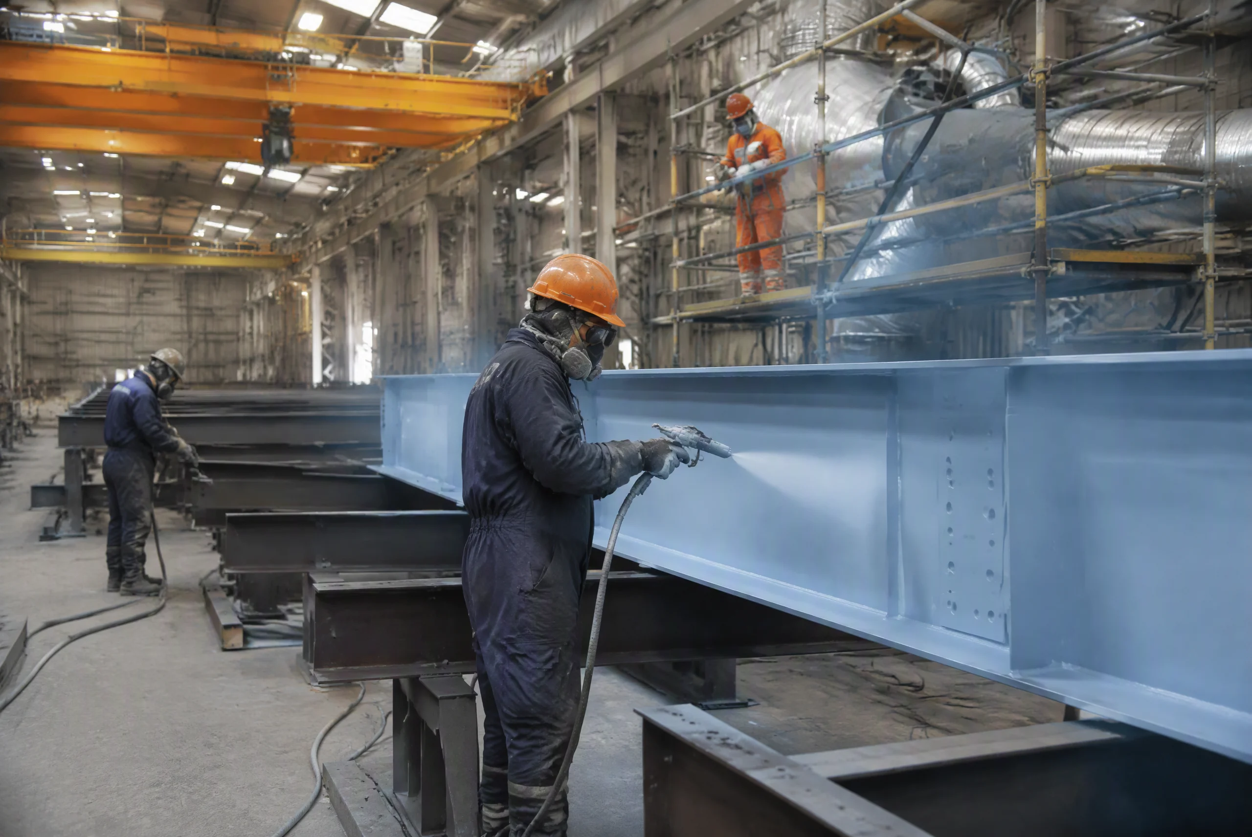
The Ground Investigation Deliverables
A steel building foundation is only as good as the ground report beneath it, and the report must be read for foundation design, not for general information. The deliverables that move the design: cone penetration tests (CPT) every 25–30 m of footprint in variable ground at 1.5–2.0 m depth intervals, SPT blow counts below the bearing zone to the depth of influence (typically 1.5 to 2 times the footing width), groundwater level recorded at the driest and wettest seasons with a piezometer observation period, and undisturbed samples for compressibility testing where settlement governs (soft clays and silts).
- Bearing capacity comes from SPT N-values or CPT tip resistance, correlated through the applicable code correlations and never extrapolated beyond the profile sampled.
- Settlement comes from the odometer curve of representative clays; where ground water is high, the buoyant unit weight is used and the excavation dewatering plan is confirmed feasible.
- Corrosivity of the groundwater against the anchor steel (sulphate, chloride, pH) decides whether galvanised, coated or epoxy-coated anchors are specified.
- The report states the groundwater table used for design uplift checks — the number that sizes the podium and below-grade foundations against flotation.
5. Differential Settlement and the 1/500 Limit
Steel frames tolerate uniform settlement almost perfectly — the whole building moves together and the structure barely notices. It is differential settlement that damages steel buildings, by three mechanisms: columns tilt and introduce unintended bending into the frame; anchor groups on the low side pick up reverse shear; and crane rails lose their alignment, which is the first thing operators notice and the last thing they accept.
GB 50007-2011 Table 5.3.4 caps the differential settlement between adjacent columns of frame structures at 0.002L for normal (non-highly-compressible) soils — that is the 1/500 limit this industry quotes. At the common 6 m column spacing, 1/500 allows 12 mm of differential movement between adjacent footings; at 12 m grid spacing, 24 mm. The numeral matters because it is small: a design that predicts more differential settlement must change the foundation system, the ground improvement, or the column spacing before the building is tendered, not after.
Crane buildings are stricter still. Rail-level alignment tolerance of the order of 1/1,000 of the span and a few millimetres of lateral offset per support are common crane manufacturer limits, which is why crane building foundations are nearly always controlled by the settlement check rather than the bearing check. The settlement analysis must be written into the geotechnical brief explicitly — asking only for bearing capacity guarantees is asking for the wrong answer.
What the 1/500 Limit Means in Cost
The differential settlement limit of 1/500 of the column spacing (GB 50007-2011, Table 5.3.4 for frame structures, which is the customary reference for steel portal and multi-storey frames) translates to 20 mm over a 10 m bay. The steel frame itself tolerates far more — portal frames routinely ride 30–50 mm of differential with only bolt-slot adjustment — but cladding panels, sliding doors, crane rails and the building envelope do not, and the 1/500 number is set for them. The consequence is practical: spring-mounted sliding door tracks, crane rail adjustment packs, and cladding joints with 20–30 mm of planned movement are cheaper than a ground-improvement programme, and deciding which path the project takes is a geotechnical conversation, not a structural one.
6. Groundwater, Durability and Corrosion of Embedded Steel
Groundwater changes the foundation problem in two directions. During construction, a water table at 1–2 m below excavation level means dewatering, and for shallow rafts the finished structure must be verified against hydrostatic uplift with empty weight — a fridge-empty building floating out of its excavation is a documented failure mode, not a theoretical one. For the steel designer, groundwater also sets the durability class of the concrete and the protection of everything embedded in it.
Embedded and buried steel protection follows a simple hierarchy. Anchor bolts are fully protected by concrete cover (40–50 mm minimum for aggressive environments per GB 50010 environmental classes) and never need paint — what they need is grout that is dense and non-shrink, because grout voids create the oxygen-and-moisture cell that corrodes embedded steel. The exposed part of base plates and columns above the slab line normally receives the building's standard anti-corrosion system (zinc-rich primer plus epoxy, per ISO 12944 for the relevant corrosivity category), and in aggressive coastal or industrial atmospheres the designer extends the protection detail explicitly across the ground-waterline interface — the point where steel passes from sheltered to exposed service is where coating breakdown is most common.
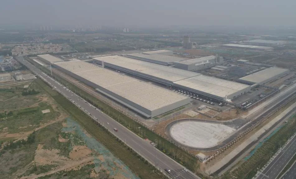
Grout and the Interface Corrosion Detail
The steel-to-concrete interface is the detail where foundations are won or lost. The base plate sits on a 25–50 mm grout bed of high-strength nonshrink cementitious grout (compressive strength typically 60–80 N/mm²), the plate is seal-welded around its perimeter where exposed, and the anchor bolts are protected through the exposed length with the same coating class as the connecting steel. Where the environment is aggressive — industrial, coastal or ground-contact — the column base is raised above the finished floor line or wrapped with a corrosion barrier, because the base plate underside is the coldest, wettest, least inspected steel in the building. Water that stands on a base plate flange is water that will reach the anchor threads, and the specification should assume it will, not hope it will not.
Key Takeaways
- Foundation selection is driven by load, bearing and settlement in that order — isolated pads for light frames, strip footings for wall and crane lines, rafts for weak soil and uplift, piles for deep soft deposits.
- Design the load path as three flows: axial into bearing, moment into a bolt-tension/concrete-compression couple, and shear through friction plus a shear key when friction is exhausted.
- Anchor bolts are a package: structural capacity, concrete breakout, and a shop-built template holding ±2–3 mm positions are all part of the same detail.
- Wind uplift often governs the anchor group. Check maximum uplift with minimum dead load; for light roofs this is the binding case, not gravity.
- The settlement limit is 1/500 between adjacent columns (GB 50007-2011), tighter for crane buildings — geotechnical briefs must request settlement parameters, not bearing capacity alone.
- Groundwater and durability are interface decisions. Concrete cover protects embedded steel; dense non-shrink grout and a proper coating transition protect the exposed-to-embedded boundary.
If you are briefing the geotechnical investigation for a steel building, or reviewing a foundation design against our steel package, our engineering team can provide the column reactions, base plate and anchor layouts, and the settlement limits that the foundation design must meet. Contact our engineering team for a coordinated structural package.
Need a Coordinated Steel and Foundation Package for Your Building?
We deliver the complete interface: column reactions and base plate designs ready for the foundation designer, anchor bolt templates for fabrication, and settlement criteria for the geotechnical brief. Send us your layout and soil data for a preliminary assessment.
Request a Consultation