
Steel Tube Truss Connections: Joint Design, Welding and Verification
In tubular trusses — the roofs of stations, stadiums and exhibition halls — the members are second to the joints. A circular hollow section (CHS) truss member reaches its theoretical capacity only if the joint it lands on can deliver that capacity; and joint design, not member design, decides the wall thickness of the chord, the weld costs, the NDT budget and half the fabrication hours. This is why almost every costly problem in tubular truss projects is a joint problem: a chord wall too thin for punching shear, a branch-chord geometry outside code validity, or a weld detail that fails its fatigue check after the roof is loaded.
This guide explains how CHS truss connections are designed, welded and verified in practice. It follows EN 1993-1-8 (Design of Joints) and the CIDECT design guides for circular hollow sections, GB 50017-2017 Chapter on tubular joints for Chinese practice, and AWS D1.1 (Structural Welding Code — Steel) for welding procedure and inspection. The recommendations reflect trusses we have fabricated for projects including the Xuzhou High-speed Railway Station roofs and the Guangzhou Baiyun International Airport Phase III expansion (450,000 m², 42,000 t of steel), where multi-branch joints were routine and every joint was verified against code capacity before fabrication.
We cover joint typology, the geometry limits that define validity, capacity and failure modes, weld design and execution, and the finite element verification points that de-risk the most loaded nodes.

1. Joint Typology: K, T, Y, N, KT and X Joints
CHS joints are classified by the number and arrangement of branches and by whether the branches overlap. The type determines which capacity formula applies, and the mis-classification of a joint is the most common review error.
- T and Y joints: a single branch framing into the chord, at an angle θ between roughly 30° and 90°. Found at truss ends and at point-loaded nodes; the governing check is chord wall punching shear and chord face plastification.
- X joints: two branches in line, one each side of the chord, transferring a through-force. Governed by chord wall crushing and local buckling at high axial chord stress.
- K and N joints: two branches on the same side of the chord (K: both compression or both tension; N: one of each). The two branch forces are balanced by shear in the chord panel between them; gap joints are the norm in trusses.
- KT joints: three branches on one side, typical at the junction of two diagonals and a vertical at a truss panel point; capacity is checked as a combination of K-joint behaviour with chord stress interaction.
- Gap versus overlap: gap joints (a clear gap g between branch toes on the chord face, usually 10–50 mm) are preferred in fabrication because the welds are accessible; overlap joints (branch-to-branch welded) carry more load but require precise fit-up and are specified only where space or capacity demands.
| Joint type | Typical configuration | Governing check | Weld preference |
|---|---|---|---|
| T / Y | Single branch, 30–90° | Punching shear, face plastification | Fillet or PJP around perimeter |
| X | Two branches opposite | Chord wall crushing | Full or partial penetration |
| K / N | Two branches, same side | Chord shear, gap geometry | Fillet, throat sized to branch |
| KT | Three branches, same side | Combined K behaviour + chord stress | Gap joints, NDT on each branch |
2. Geometry Limits: Diameter and Wall Thickness Ratios
Code capacity formulas for CHS joints are valid only inside a stated geometry envelope; outside it, the joint must be verified by testing or finite element analysis. EN 1993-1-8 Table 7.1 sets the limits for circular sections:
- Diameter ratio β = d1/d0 between 0.2 and 1.0 (practical design keeps β ≤ 0.8 to control chord wall punching and weld accessibility).
- Wall thickness ratio τ = t1/t0 between 0.2 and 1.0 — the branch wall is normally thinner than or equal to the chord wall.
- Chord slenderness d0/t0 between 10 and 50, with the practical band 20–35 for truss chords to resist local buckling and ovalisation.
- Branch angle θ ≥ 30° for K joints and 30–90° generally; below 30° deflection and weld profiles become unmanageable.
- Gap conditions: for gap K joints, the gap g must fall inside the code range; a gap too small behaves as an overlapping joint, and one too large changes the load path.
GB 50017-2017 applies the same family of limits for axially loaded CHS joints (its tubular joint chapter mirrors the CIDECT envelope with Chinese factors), so a joint designed inside these limits is transferable between the two systems apart from partial factors. A typical station roof joint — chord φ351×16 with branches φ180×8 at 45° — has β = 0.51, τ = 0.5 and d0/t0 = 22, comfortably inside validity, and its capacity is governed not by the branch but by the chord wall towards punching shear.
3. Capacity Checks and Failure Modes
Four failure modes cover nearly all CHS joint design, and each maps to a code formula:
- Chord face plastification (gap K and T/Y joints): the branch forces deform the chord wall locally. Governed by the chord yield strength, wall thickness and the branch footprint; the EN 1993-1-8 factorised equations for N1,Rd apply to the chord wall, not the branch section.
- Chord wall punching shear: the branch perimeter tries to punch through the chord wall; capacity scales with the chord wall thickness t0 and the chord yield strength fy0, and this is usually the check that forces a heavier chord wall in trusses with stocky branches.
- Chord stress interaction: a chord already loaded in compression or tension has reduced joint capacity; EN 1993-1-8 applies a reduction factor to the joint resistance depending on the chord utilisation n. This is why the same joint can be adequate at mid-span of a truss and inadequate at the supports — the chord force is different, the geometry identical.
- Local buckling: at high d0/t0 or under chord compression, the chord wall or branch can buckle locally before the joint force is reached; this is the check that limits how thin a large chord may be.
In design we size the chord wall from the worst joint in the truss, not from the member axial check — in most tubular trusses the joints, not the soffits, set the chord wall thickness. A useful heuristic from our shop records: a 12–16 mm chord wall typically serves spans up to 40 m; beyond that, joint demand pushes chords to 20 mm and above or forces the designer to reinforce nodes locally (collar plates or internal ring stiffeners).
4. Weld Design and Execution: AWS D1.1 and GB 50661
The weld around a branch is a curve in space, and its design follows three rules. First, the weld must develop the branch capacity: for slim branches (β low, branch thin), a fillet weld with throat thickness approximately 0.7–0.8× the branch wall achieves full-strength; for stocky branches, partial-penetration or full-penetration butt welds are required, with the penetration depth verified on procedure qualification. Second, the weld profile must follow the intersection geometry: at the heel of the branch the weld is long but deep, at the toe it is short; the profile is rolled (radiused) at heel and toe transitions to reduce the stress concentration that matters for fatigue. Third, weld execution is procedure-qualified and inspected — AWS D1.1 prequalified PJP/CJP details and GB 50661 qualified WPS, welder certification, and NDT: ultrasonic testing on all full-penetration welds at primary joints per GB/T 11345, and magnetic particle testing on fillet welds at highly stressed nodes.
Overhead welding at the branch underside is unavoidable in shop fabrication but should be minimised: CNC profiling of the branch end (the three-dimensional miter cut) must match the chord radius within 1–2 mm, and the joint is rotated in the positioner so that as much weld as possible is made in the flat or horizontal position. Weld root condition at the heel where access is tightest is the most common NDT rejection point, and a review of NDT records for any tubular truss proposal should look for exactly that pattern.
Weld Throat Check in One Line
For the fillet welds that join brace members to the chord at the gap between K-joint braces, the design check reduces to a throat area equation that every shop engineer can apply before the finite-element model is opened:
a ≥ N / (lw · fw) with a = throat (leg × 0.7), lw = effective weld length along the brace perimeter, fw = design shear strength of the weld (e.g., 160 N/mm² for E50 filler on S355-class parent per GB 50017 formulations)
Because the weld follows the wrapped intersection line, the effective length lw is only 60–80% of the full intersection perimeter in practice — the overlap regions and the acute angles at the heel and toe cannot carry load uniformly. Applying this correction is the difference between a weld that passes by 10% and one that is 30% under-utilised at the first weld check.
5. Finite Element Verification Points
Code formulas cover the standard envelope, but three situations deserve shell or solid FE verification before fabrication, and in our workflow they are mandatory: complex nodes (KT and multi-branch at supports), joints outside the geometry envelope, and joints on the fatigue-critical load path of the structure.
- Model the true geometry: mesh the chord and branches with the actual intersection curves, gap dimension and weld profile; linear solid elements at the weld toe are the baseline for meaningful local stress.
- Check capacity locally: the FE von Mises peak in the chord wall under ULS loads is compared against the governing code capacity — the target is agreement with the code check within 10–15%; larger differences flag either an FE modelling error or a joint the code formulas are not intended to cover.
- Check local buckling: for high d0/t0 chords, run a buckling eigenvalue analysis on the joint sub-model with the chord axial force at design level; the local buckling mode must stay clearly above the design load.
- Fatigue verification: where the truss is fatigue-sensitive (bridges, crane-supporting, railway station roofs over tracks), use the hot-spot stress method with stress concentration factors extracted from the FE model per EN 1993-1-9, against the appropriate detail category and cycle count.
- Document the model: geometry source, mesh density at the weld toe, boundary conditions and the extraction points for hot-spot stress must be recorded; an FE check that cannot be reproduced is a liability, not assurance.
What the FE Model Must Reproduce
The finite-element verification of a tubular joint earns its place when it reproduces four behaviours that the code hand-check cannot: the ovalisation of the chord cross-section under brace compression (the defining deformation of an unstiffened joint), the stress gradient around the intersection line (peak stress at the heel, low at the sides), the through-thickness stress in the chord wall at the gap region, and the elastic-plastic redistribution at the design resistance. The model uses solid or thick-shell elements through the wall thickness, fixes the chord ends at lengths of 6–10 chord diameters to avoid boundary effects, and is validated against the code capacity before it is used to extend it — the model that does not first match the hand-capacity is not verified, it is merely computed.
6. Fabrication Practice: From Shop Drawings to Pre-Assembly
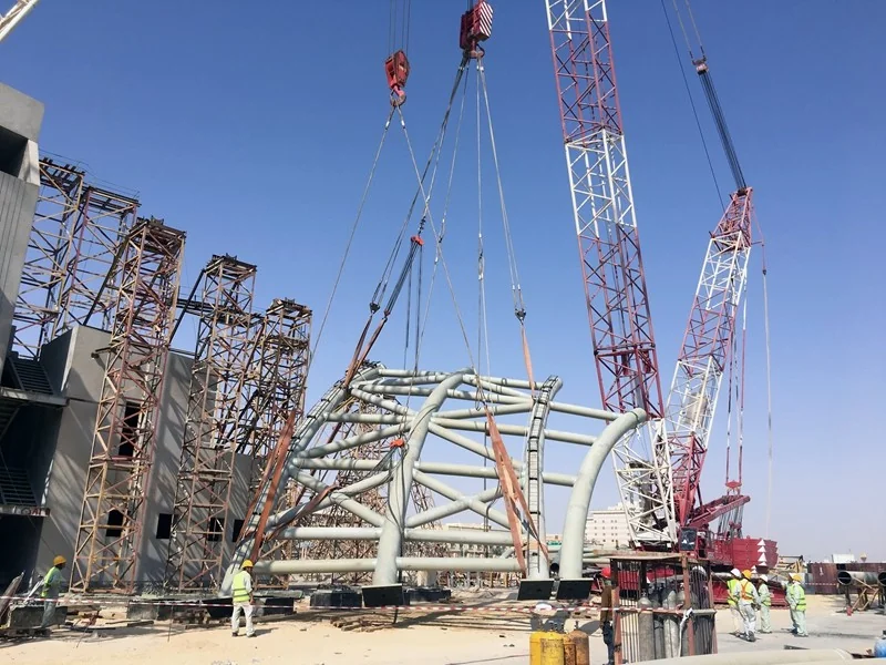
A tubular truss is fabricated by profiling every branch end in three axes, dry-fitting the joint to check gaps, welding in the positioner, and verifying the truss geometry after welding when distortion is present. The two shop controls that decide field success are tolerances and sequence. Chord lengths are held to ±2 mm at splice points; branch intersection geometry to ±2 mm; and the truss is cambered and pre-assembled so that field closures at splice sections match — every pipe truss we ship is dry-assembled in the workshop with the field splice bolts fitted before painting.
Welding sequence controls distortion on long chords: balanced welding around each joint, chords welded from mid-span toward supports, and the truss held in its cambered jig until cool. For multi-branch nodes, the branches are welded in an order that lets each weld cool before the next applies its shrinkage, and the node is checked by gauge at each stage. This discipline is why on projects like the Xuzhou High-speed Railway Station roofs, the field erection of welded tubular trusses proceeded without rework at the joints — the joints were made in the workshop, and the field was a closure operation.

Pre-Assembly QA Acceptance
Before tubular trusses leave the workshop, pre-assembly acceptance locks the geometry that the site will never re-check: chord camber measured at every panel point against the shop drawing tolerance (±3–5 mm typical for long spans), bolt hole alignment by drift-pin insertion, the intersection-line profiles of the K-joints verified by template striking against the chord surface, and the weld NDT records matched to the weld map member by member. The acceptance record is the bridge between the finite-element verification and the site: the joint that the analysis assumed must be the joint that was built, and the QA sheet is the only proof of continuity.
Key Takeaways
- Classify the joint correctly first. T/Y, X, K/N and KT joints each have their own capacity formula; mis-classification is the most frequent review and modelling error.
- Stay inside the geometry envelope. EN 1993-1-8 and GB 50017-2017 limits: β = 0.2–1.0, τ = 0.2–1.0, d0/t0 = 10–50, branch angle ≥ 30° — outside it, only testing or FE can justify the joint.
- The chord wall sets the joint capacity. Punching shear and chord stress interaction usually govern; size the chord from the worst joint, not from the member check.
- Weld to develop the branch, not a nominal size. Fillet throat 0.7–0.8×t1 for slim branches, penetration welds for stocky ones, rolled profiles at heel and toe, and NDT per AWS D1.1 / GB 50661.
- Verify complex and fatiguable nodes in FE with real geometry, weld profile, local buckling and hot-spot stress, documented for reproduction.
- Fabrication discipline is the finish line: CNC profiling, welding sequence, camber jigs and full pre-assembly turn joint design into joints that fit on site.
If your project uses tubular trusses — station roofs, stadium canopies, airport terminals — our engineering team can review or produce the joint design, weld specifications and shop drawings, and our workshops can fabricate and pre-assemble them with the NDT records attached. Contact our engineering team for a joint design review or fabrication enquiry.
Need Tubular Truss Joints Designed, Verified and Fabricated Correctly?
With qualified joint design per EN 1993-1-8, GB 50017 and AWS D1.1, CNC profiling and full pre-assembly in our workshops, we deliver pipe trusses that fit on site and carry their design loads with the NDT records to prove it. Send us your truss geometry and loads for a joint design review.
Request a Consultation