
Steel Aircraft Hangars — Wide-Span Maintenance & Parking Facilities
A hangar is the largest single-door building most structural engineers will ever design. The door opening itself may span 60-150 metres with zero intermediate columns, the clear height must accept an A380's 24.1 m tail fin, and the roof must carry overhead cranes of 20-80 tonnes where maintenance work takes place directly below. Every kilogram of steel is a safety decision made twice: once for the structure, once for the aircraft inside it.
Five Load Cases That Define Hangar Structure
Before a single member is sized, five load cases must be answered with numbers from the airline's operations manual, the crane supplier's catalogue and the local airport authority.
The door is a structural element, not an opening. A 90 m wide maintenance hangar door must be rigid enough to withstand the hangar's wind suction, its own 300-500 kN weight, and the fatigue of opening 20-40 times per day. We engineer the door as a lattice beam system supported on travelling bogies, with the parent structure providing the overhead rail for the door's top suspension. The door-frame portal at the opening end is typically a welded box-column and lattice girder combination, sized so the deflection under door-girder loads does not exceed L/1200 at the opening.
Overhead cranes impose dynamic design regimes. Aircraft maintenance hangars use overhead bridge cranes of 10-80 tonnes with spans up to 90 m. The crane runway girders are designed to Class A5-A7 duty per GB 50017, with wheel loads from the supplier's data, lateral surge taken as 10% of the hook load, and longitudinal traction as 5%. Fatigue verification follows EN 1993-1-9 (detail category 112 for welded runway beams with bolts) for the 2 million load cycles a busy MRO base experiences.
Documented load on the roof. A hangar roof must support maintenance platforms, lights, cable trays and, in arctic or tropical climates, substantial wind (up to 0.85 kN/m² basic pressure) and snow (up to 1.0 kN/m² on the ground, 0.6-0.8 on the roof). The roof structure of a 100 m hangar is usually a welded pipe space truss at 9-15 m intervals covered by sandwich panels, or a bi-directional space frame for spans beyond 120 m.
Explosion and blast loads in fuelling zones. Hangars with fuelling pits and SEP (stationary engineering plant) zones require blast-mitigation design for the door structure and window openings per API 752 and NFPA 415 where a hydrogen or fuel vapour cloud scenario is credible. The blast overpressure of 10-50 kPa at the building face is converted to equivalent static loads, and the door-leaf lattice is designed to remain elastic.
Seismic response of a wide, flexible diaphragm. The 90-150 m free span creates a structure whose fundamental period is 1.5-2.5 seconds, far above the 0.1-0.5 s of a conventional warehouse. In seismic zones (GB 50011, intensity 7-8), the response spectrum amplification must be calculated for the actual period, and the roof diaphragm's in-plane stiffness budgeted between the truss system and the lateral frames. We use either a rigid-framed longitudinal axis or X-braced bays at 12-18 m intervals to carry the seismic shear to the foundation.
The common thread: hangar engineering is done to the absence of failure not to the appearance of safety. Every connection in a hangar is designed for the combination of crane, door, wind, snow and seismic load that the code demands, then checked again against the operator's actual equipment — because a crane manufacturer's catalogue load rarely matches an airline's maintenance manual exactly, and the difference is never small.
Four Hangar Configurations We Deliver
Each starts from the aircraft fleet it must serve, stated in numbers, priced accordingly.
Full Maintenance & Overhaul Hangars
Complete aircraft maintenance bases for wide-body fleets. 90-150 m door spans for 2-4 aircraft positions, 20-35 m clear height, 20-80 t cranes, deep maintenance pits, and adjacent workshops.
- Door span: 90-150 m, clear height 20-35 m
- Cranes: 20-80 t bridge cranes, Class A5-A7
- Accepts: A320/A330/A350/B737/B777/B787, A380
- Roof: welded pipe truss or bi-directional space frame
Aircraft Parking & Storage Hangars
Multi-bay parking and storage hangars for aircraft between flights, with simpler door configurations (2-4 independent doors of 40-80 m) and bridge crane support for engine removal.
- Door span: 40-80 m per bay, 2-4 bays
- Clear height: 12-16 m for narrow-body parking
- Lighting: 200-300 lux average, no maintenance platforms
- Fast erection: 10-14 weeks for 10,000 m² footprint
Nose-Dock & Line Maintenance Units
Compact nose-in maintenance docks for transit checking. 30-60 m door spans, working platforms at 2-3 levels, designed for quick turnaround between pax flights.
- Door span: 30-60 m, single or split-leaf
- Platforms: 2-3 working levels at 5-6 m spacing
- Utilities: 400/230 V, compressed air, water, oxygen
- Compatible: all narrow-body fleets
Helicopter & General Aviation Hangars
Smaller hangars for rotary-wing and GA fleets. 20-40 m door spans, clear heights of 6-10 m, designed to be heated, ventilated, and blast-protected for fuelling areas.
- Door span: 20-40 m, clear height 6-10 m
- Structure: portal frame or small space frame
- Heating: 15-25 °C design for sensitive electronics
- Accepts: EC135, AW139, Mi-8, R44
Six Engineered Details of a Hangar Frame
What distinguishes a hangar from a large warehouse, item by item.
Door-End Space Truss Portal
The door-end frame is a welded box-column (typically 800×800×30 mm) and lattice girder portal, sized so the 60-150 m opening deflects less than L/1200 under door-girder and wind loads, and the whole assembly slews as a rigid frame during door operation.
80 t Overhead Crane Runway
Runway girders are continuous welded I-sections with 1.15-1.25 dynamic factor, lateral-torsional buckling verified per EN 1993-1-1, and fatigue detail categories per EN 1993-1-9. Runway level tolerance: ±3 mm over 90 m length for smooth crane travel.
Bi-Directional Space Frame Roof
Spans beyond 120 m use bi-directional space frames on a 3 m × 3 m grid of welded spherical nodes, achieving 25-40 kg/m² roof steel weight at 90 m span while leaving the entire underside column-free for crane and platform movement.
Fold-Door & Telescopic Door Systems
For very wide openings, vertically-folding lattice doors in 2-4 leafs or telescopic sliding doors in 4-6 panels are integrated with the structure. Door drive motors sized for 300-500 kN leaf weight with 2 m/min operating speed and wind-trip lockup at 20 m/s.
Composite Sandwich Envelope
Roof and walls use 100 mm PU/PIR sandwich panels with 0.5 mm Galvalume faces, achieving U-values of 0.3-0.4 W/m²·K, tested to EN 14509, with hidden fixing and 35-year durability for coastal airport atmospheres.
100% Bolted Site Assembly
All hangar members are fabricated, trial-erected and marked in the workshop; site joints use M20-M30 high-strength bolts of grade 10.9S TSG (torsion-shear type). A 15,000 m² hangar erects in 14-18 weeks including crane runways and door rails.
Codes Applied to Hangar Design & Fabrication
Structural Design
GB 50017 (steel design), GB 50009 (loads), GB 50011 (seismic), GB 50191 (dynamic loads) for Chinese projects; EN 1990/EN 1993 for European projects; AISC 360/ASCE 7 for North American projects. Hangar-specific guidance: FAA AC 150/5370-2G for airport construction, ICAO Annex 14 for apron interface, NFPA 415 for hangar fire separation, and API 752 for blast evaluation where fuelling is co-located.
Fabrication Quality
Fabrication and inspection to EN 1090-2 (Execution Class EXC3 for primary members), ISO 3834-2 (welding quality), ISO 9001:2015, GB 50205 (steel construction acceptance), with 100% ultrasonic testing of full-penetration welds on door frames and crane runway girders in accordance with ISO 17640 Level B.
Corrosion Protection
Hot-dip galvanizing to ISO 1461 with 85 μm coating on secondary steel, zinc-rich epoxy + polyurethane paint systems on primary members to ISO 12944 (C4 coastal or C5 industrial atmospheres, 25-year design life). Airside hangars in coastal airports upgrade to duplex systems — galvanizing under epoxy/polyurethane topcoat.
Airport Structures We Have Already Built
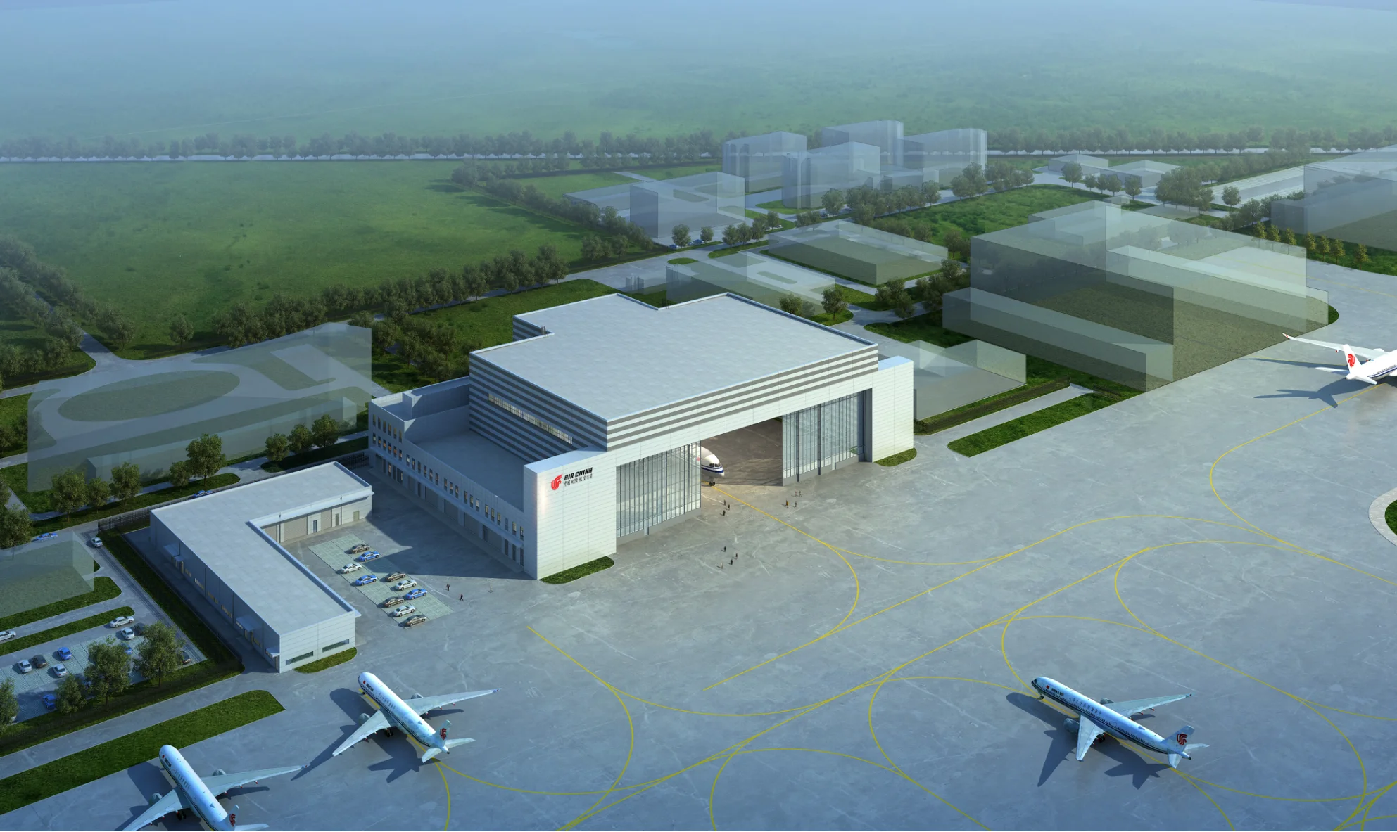
Permanent Steel Structure has delivered landmark aviation structures, including the Guangzhou Baiyun International Airport Terminal 3, where a 450,000 m² roof with 54 m clear spans was designed, fabricated and erected with 42,000 tonnes of steel; the Xuzhou Guanyin Airport Terminal; the Doha International Airport expansion; and the Airport of the Republic of the Congo. On the maintenance side, our portfolio includes Air China Beijing maintenance base facilities and Shandong TAECO aircraft maintenance facilities — both wide-span hangar projects with overhead crane runways, maintenance pits and door systems fabricated and erected by our Xuzhou works.
These are not isolated references: they are evidence of the fabrication capacity (300,000 m² of plant, 200,000 tonnes of annual capacity), the execution discipline (Class A5-A7 crane runway fabrication to ISO 17640 Level B UT acceptance), and the Antarctic-grade logistics experience (delivering structural steel to the Ross Sea where temperatures reach -28 °C at 60 m/s wind) that hangar projects demand — because an aircraft maintenance base, like a polar station, cannot be redesigned on site.
Planning a Hangar or Aviation Facility?
Send us the fleet composition (up to 3 aircraft types), the hangar function (MRO, parking, nose-dock), door configuration requirements, and local wind/snow/seismic data. We return a structural scheme, member schedule, steel weight and erection program within two weeks.
Email: market@permanentsteelstructure.com | WhatsApp: +86 18621689980 | Phone: +86 516-83269982