
Welded Sphere Grid Structures — Built for Permanent Rigidity
When a structure must stand for 50 years under heavy industrial loads, thermal cycling, and seismic activity, bolted connections introduce a variable that welded connections eliminate: the risk of bolt loosening. Welded sphere grids fuse every node into a monolithic structural system — no bolts to inspect, no preload to lose, no joints to retighten.
Welded for Life: Why Monolithic Beats Bolted in Heavy-Duty Applications
Bolted sphere grid structures excel where speed, transportability, and future disassembly matter. But when the requirement is a permanent, heavy-duty roof that must carry concentrated loads, survive decades of thermal cycling, and resist seismic forces without any connection maintenance — welded sphere grids are the engineering choice.
The fundamental difference lies at the node. A bolted sphere node relies on high-strength bolts threaded into forged steel spheres. Over 30 years of thermal expansion and contraction, vibration from machinery, and wind-induced fatigue, bolt preload relaxes. Every bolted connection is a maintenance item — it must be inspected, and if preload has dropped, retightened. In a grid with 2,000 nodes, that is 2,000 potential failure points.
A welded sphere node eliminates this variable entirely. The steel tube is joined to the sphere by a full-penetration butt weld. Once welded, the connection becomes part of the sphere itself — a continuous steel path with no mechanical interface to loosen, no preload to lose, no gasket to degrade. The node is as permanent as the steel it is made from.
This is why welded sphere grids are specified for power plant coal sheds, heavy industrial workshops, and structures in seismic zones where connection integrity under cyclic loading is not a maintenance question but a survival question.

What Is a Welded Sphere Grid Structure?
A welded sphere grid is a spatial structure system where steel tubes connect at nodes formed by hollow steel spheres, with every tube-to-sphere joint executed as a full-penetration weld.
The welded sphere grid shares the same spatial topology as its bolted counterpart — a network of steel tubes arranged in triangulated modules (typically square-on-square, square-on-diagonal, or triangular pyramids) that distribute loads through axial member forces rather than bending. What changes is the node.
In a welded sphere system, each node consists of a hollow steel sphere fabricated from two pressed steel plate hemispheres welded together at the equator. The steel tubes meet the sphere surface at engineered angles, and each tube end is prepared with a bevel groove to enable a full-penetration butt weld directly to the sphere shell.
Because there are no bolt holes, no sealing plates, and no threaded connections, the node is a monolithic steel assembly. The sphere shell, weld metal, and tube wall form a continuous load path. This provides several structural advantages:
- Higher node rigidity — welded joints approach full fixity, increasing the grid's resistance to buckling and vibration
- Greater load capacity per node — the weld cross-section can be larger than a bolt shank, transferring more force per connection
- No bolt relaxation — thermal cycling and vibration cannot reduce connection stiffness over time
- Simplified long-term maintenance — no bolt torque inspection program required; only visual weld inspection per maintenance schedule
Sphere Construction
- Sphere body: Two steel plate hemispheres, hot-pressed from Q355B / Q345B plate, typically 4–24mm wall thickness
- Equatorial weld: Full-penetration butt weld joining the two hemispheres, ultrasonic-tested
- Tube connection: Bevel-groove full-penetration weld directly to sphere shell surface
- Welding standard: GB 50661 / AWS D1.1, qualified welders, WPS-controlled
- NDT: Ultrasonic testing (UT) 100% of structural welds per GB/T 11345
Welded vs Bolted Sphere Grid: Choosing the Right System
The choice between welded and bolted sphere grids is not a question of which is better — it is a question of which structural requirements govern the project.
| Parameter | Welded Sphere Grid | Bolted Sphere Grid |
|---|---|---|
| Node type | Hollow steel sphere, two welded hemispheres | Forged steel sphere, CNC-drilled threaded holes |
| Connection method | Full-penetration butt weld | 10.9S high-strength bolt through sealing cone |
| Node rigidity | Approaches full fixity (monolithic) | Semi-rigid (bolt slip possible under extreme load) |
| Typical span range | 40–120m (heavy loading) | 30–150m (lighter loading) |
| Steel consumption | 25–40 kg/m² | 15–30 kg/m² |
| Assembly speed | Slower (field welding required) | Fast (bolted, no field welding) |
| Disassembly | Not practical (welded joints are permanent) | Fully disassemblable and relocatable |
| Long-term maintenance | Visual weld inspection only | Bolt torque verification program required |
| Ideal application | Permanent heavy-duty roofs, power plants, seismic zones | Transportable structures, temporary roofs, rapid deployment |
In practice, many large-span structures use a hybrid approach: bolted sphere grids for the main roof area (for speed and weight efficiency) with welded connections at critical load-transfer nodes (where maximum rigidity is required). Our engineering team determines the optimal mix based on load path analysis, not on a preference for one system over the other. Learn about our bolted sphere grid capabilities →
Manufacturing Process: From Steel Plate to Ultrasonic-Tested Node
Every welded sphere grid we manufacture follows a controlled six-stage process with non-destructive testing at every weld stage.
-
1
3D Structural Modeling & Node Design
The grid is modeled in spatial structural software with all load cases. Each node's connection forces determine sphere wall thickness, weld bevel geometry, and tube end preparation. Member forces extracted for connection design per GB 50017. -
2
Sphere Hemisphere Pressing
Steel plate (Q355B / Q345B, 4–24mm) is hot-pressed into hemispheres using hydraulic forming dies. Dimensional accuracy of the pressed hemisphere directly affects weld fit-up quality. Spheres are typically 180–500mm diameter for grid applications. -
3
Equatorial Weld & Sphere Finishing
The two hemispheres are joined by a full-penetration butt weld at the equator using submerged arc welding (SAW) or gas-shielded flux-cored arc welding (FCAW-G). The equatorial weld is ultrasonic-tested per GB/T 11345 before the sphere enters tube-welding. -
4
CNC Tube Cutting & Bevel Preparation
Q355B steel tubes are cut to design length on automated CNC band saw lines. Tube ends are bevel-grooved at the specific angle required by each node's geometry — no two bevel angles in a curved grid are necessarily identical. -
5
Tube-to-Sphere Welding
Tubes are fitted to the sphere at the engineered angle and welded with full-penetration bevel groove welds using qualified WPS. Welder qualification, preheat temperature, and interpass temperature are controlled per welding procedure specification. -
6
100% Ultrasonic Testing & Anti-Corrosion
Every structural weld is ultrasonic-tested per GB/T 11345. Defective welds are ground out and re-welded with re-testing. After NDT clearance, the grid receives anti-corrosion treatment: abrasive blast cleaning to Sa2.5, followed by epoxy zinc-rich primer + polyurethane topcoat rated for the service environment (C3–C5).
Where Welded Sphere Grids Are the Engineering Answer
Each application below represents a structural challenge where welded connections are specified not by preference but by requirement — bolted connections would introduce unacceptable maintenance or reliability risks.
 Power Plants
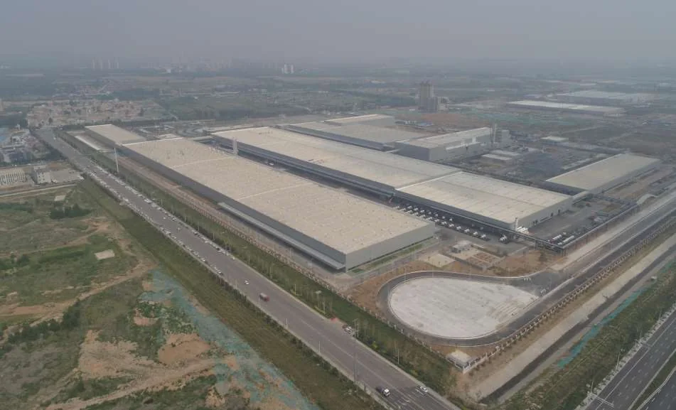
Power Plant Coal Sheds
Challenge: Coal storage sheds at thermal power plants must span 90–120m to accommodate stacker-reclaimers. The environment is aggressively corrosive — coal dust, sulfur compounds, and moisture attack steel surfaces continuously. Vibration from machinery and conveyor systems transmits into the roof structure.
Why welded: Bolted connections in a corrosive, high-vibration environment require periodic torque inspection — a maintenance program that is difficult to execute on a roof 30m above active coal handling. Welded nodes eliminate this maintenance burden entirely. The monolithic weld also provides better corrosion resistance than a bolted joint with crevices where moisture and chloride can accumulate.
 Heavy Industrial
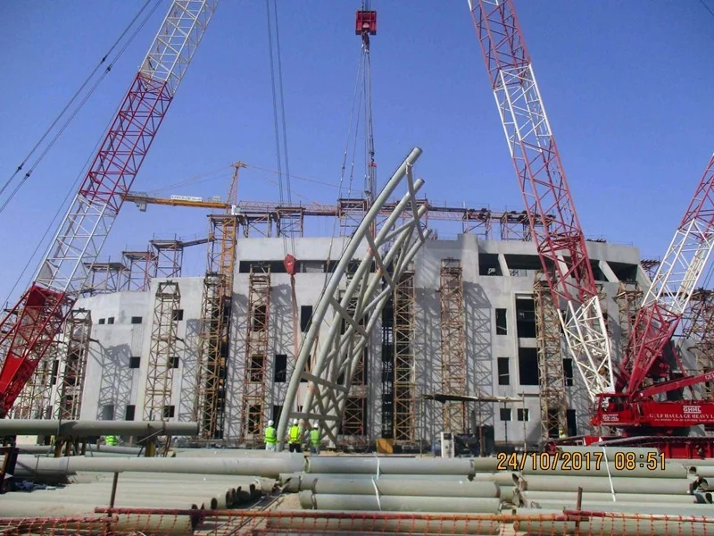
 Workshops
Challenge: Workshops for steel mills, cement plants, and heavy machinery assembly carry concentrated loads from overhead cranes (50–200t capacity), process equipment suspended from the roof, and potential impact loads from material handling.
Why welded: Concentrated and dynamic loads demand maximum node rigidity. A bolted connection under repeated heavy loading risks bolt fatigue and preload relaxation. Welded nodes approach full fixity, distributing concentrated loads more effectively into the grid topology and providing inherent damping against dynamic crane loads.
 Seismic Zones
Seismic Zone Structures
Challenge: In regions with seismic design intensities of 7–9 degrees (GB 18306), grid roof structures must survive cyclic loading that reverses tension and compression in members multiple times per event. Bolted connections under reversed cyclic loading can experience bolt hole elongation and progressive preload loss.
Why welded: A full-penetration weld has no mechanical interface to loosen under reversed loading. The connection behaves elastically through the steel material itself, with fatigue life governed by the base metal properties rather than bolt preload retention. Welded grids are the preferred system when seismic performance per GB 50011 governs the connection design.
Welded Sphere Grid Technical Specifications
| Steel tube material | Q355B / Q345B (yield strength ≥ 355 MPa) |
| Sphere material | Q355B / Q345B steel plate, hot-pressed hemispheres |
| Sphere diameter | 180–500mm (standard range); custom sizes available |
| Sphere wall thickness | 4–24mm (determined by node forces) |
| Tube diameter range | φ60–φ219mm (standard); larger sizes for heavy-load nodes |
| Welding process | SAW (equatorial), FCAW-G or GMAW (tube-to-sphere), full-penetration bevel groove |
| Welding standard | GB 50661 / AWS D1.1, qualified WPS and PQR |
| Non-destructive testing | Ultrasonic testing (UT) 100% per GB/T 11345, Grade II acceptance |
| Typical span range | 40–120m (welded grid under heavy loading) |
| Steel consumption | 25–40 kg/m² (span and loading dependent) |
| Anti-corrosion system | Sa2.5 blast cleaning + epoxy zinc-rich primer + polyurethane topcoat (C3–C5) |
| Design codes | GB 50017, JGJ 7, GB 50009, AISC 360 (on request) |
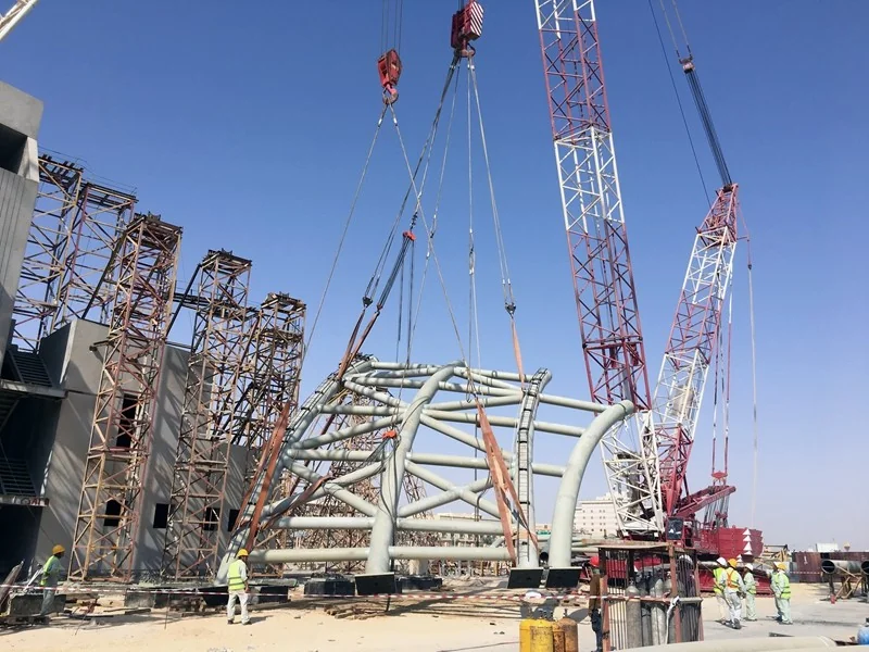
Full-Industry-Chain Welded Grid Manufacturing Since 1999
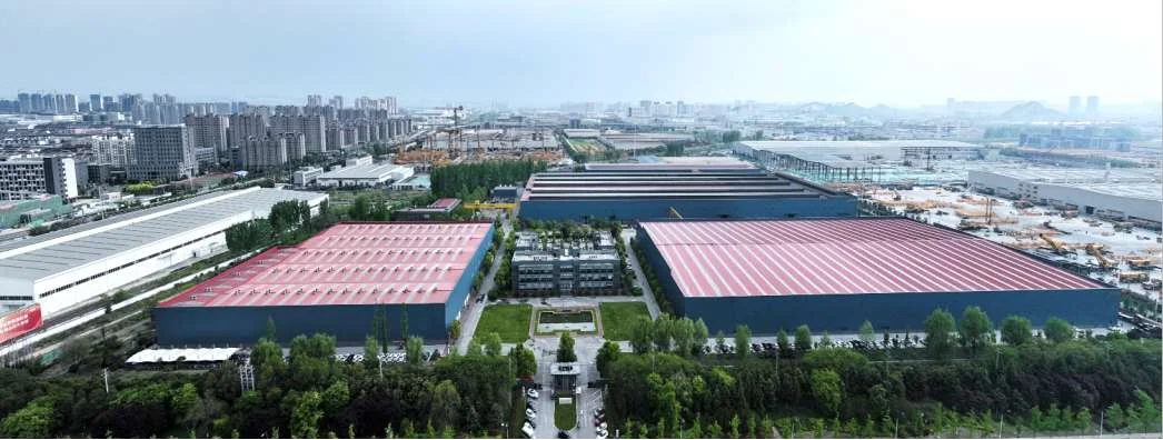
Welded sphere grid fabrication is one of our 10 core manufacturing technologies. We do not subcontract sphere pressing, welding, or NDT. Every stage from steel plate procurement through final anti-corrosion coating happens within our 100,000m² manufacturing base in Xuzhou.
Our 200,000-ton annual steel structure capacity and 6 top-level national qualifications mean we can deliver welded grid projects of any scale. Our 50+ R&D engineers and 100+ patents include innovations in sphere welding technology, weld distortion control, and automated ultrasonic scanning systems.
When you specify a welded sphere grid from Permanent Steel, you are not buying steel by the ton. You are buying an engineered structural system from a manufacturer that has been building steel structures for over 25 years — with a world-record 229m span beam-string structure in our project portfolio.
Welded Sphere Grid System Specifications
| Parameter | Light Grid | Medium Grid | Heavy Grid |
|---|---|---|---|
| Sphere diameter | Φ200–300mm | Φ300–500mm | Φ500–800mm |
| Tube diameter | Φ60–114mm | Φ114–180mm | Φ180–325mm |
| Tube wall | 3.0–5.0mm | 5.0–10.0mm | 10.0–20.0mm |
| Steel grade | Q235B/Q355B | Q355B | Q355B/Q390B |
| Typical span | 20–40m | 40–80m | 60–120m |
| Grid depth | 1.5–3.0m | 3.0–5.0m | 4.0–8.0m |
| Load capacity | 1.0–2.5 kN/m² | 2.5–4.5 kN/m² | 4.0–8.0 kN/m² |
| NDT level | UT 20% Gr.II | UT 100% Gr.II | UT 100% Gr.I + RT 10% |
Sphere Weld Quality & Ultrasonic Testing
In a welded sphere grid, the sphere-to-tube weld is the most critical connection in the entire structure. Every weld is tested — not sampled.
Sphere Manufacturing Quality
Each welded sphere is manufactured from two steel hemispheres pressed from steel plate and joined by a full-penetration circumferential weld. Quality control points include:
- Plate material verification: Mill test certificate reviewed for yield strength, tensile strength, and elongation per GB/T 1591
- Hemisphere forming: Press-formed from plate; wall thinning at equator < 10% of nominal thickness
- Equatorial weld: Full-penetration SAW or GMAW weld joining the two hemispheres; 100% UT tested per GB/T 11345 Grade II
- Dimensional check: Sphere diameter within ±1.5mm; sphericity (out-of-round) < 1.5mm
- Weld preparation: Bevel angle 60±5°; root face 1–2mm; root gap 3–4mm for full penetration
Sphere-to-Tube Weld
The connection between the steel tube member and the sphere is the structural heart of the grid. The tube end is bevelled and full-penetration welded directly to the sphere surface. Quality controls include:
- Tube end preparation: CNC bevel cutting with bevel angle 30–35° for full-penetration groove weld
- Fit-up inspection: Root gap 3–5mm; tube axis aligned to sphere center within ±1°
- Welding: GMAW multi-pass welding with preheat (100°C for tube wall ≥ 8mm)
- UT inspection: 100% of sphere-to-tube welds ultrasonic tested per GB/T 11345 Grade II (Grade I for seismic-critical structures)
- Visual inspection: Weld profile, undercut, surface porosity per GB 50661 acceptance criteria
Full-Structure Load Testing
For critical applications (power plant coal sheds, heavy industrial workshops in seismic zones), we conduct full-scale load testing of prototype grid panels:
- Test setup: A representative grid panel (typically 3×3 bays) is assembled on a test frame with hydraulic loading actuators
- Loading sequence: Incremental loading to 0.5×, 0.75×, 1.0× design load, with deflection measurement at each stage
- Acceptance criteria: No permanent deflection exceeding L/500 at 1.0× design load; no weld cracking or member buckling at 1.5× design load (safety factor verification)
- Reporting: Full test report with load-deflection curves, strain gauge data, and visual inspection records
Design Standards
- JGJ 7 — Technical specification for space frame structures
- GB 50017 — Standard for design of steel structures
- GB 50205 — Acceptance of construction quality of steel structures
- GB 50661 — Code for welding of steel structures
- GB/T 11345 — Ultrasonic testing of welded joints
- GB 50011 — Code for seismic design of buildings
- GB/T 1591 — Low-alloy high-strength structural steels
- GB/T 709 — Dimensions and tolerances for steel plates
Why Permanent Steel for Welded Sphere Grids
Permanent Steel has manufactured welded sphere grid structures since our founding in 1999. Our 300+ mu manufacturing base in Xuzhou includes dedicated sphere pressing, CNC tube cutting, and assembly stations specifically configured for heavy-duty grid production. With 200,000 tons of annual manufacturing capacity and 3,000,000m² of annual construction, we have the volume capability for large coal shed and heavy industrial projects.
Our 50+ R&D engineers perform complete structural design per JGJ 7, including finite element analysis of the grid under gravity, wind, seismic, and thermal loads. Every sphere-to-tube weld is 100% ultrasonic tested per GB/T 11345, with full traceability from material certificate to NDT report. We hold 6 top-level qualifications and 100+ patents in steel structure technology — including innovations in welded sphere forming and connection design.
Full-Chain Delivery
- Design: Structural design, connection design, and fabrication drawings in-house
- Manufacturing: Sphere pressing, tube cutting, welding, and NDT under one roof
- Installation: Experienced erection teams for grid assembly at height
- Quality: ISO 9001 QMS with full material and NDT traceability
- Certifications: 6 top-level qualifications including Special-Class spatial grid structure design and manufacturing
- Track record: Coal sheds, heavy industrial workshops, and seismic-zone structures delivered since 1999
For power plant coal sheds, heavy industrial workshops, and structures in seismic zones where maximum rigidity and permanent connections are non-negotiable, a welded sphere grid from Permanent Steel is engineered to perform for decades without connection loosening or bolt fatigue. Our engineering team is ready to review your project requirements and provide a detailed technical proposal.
Have a Heavy-Duty Grid Project? Let Us Engineer It.
Send us your loading conditions, span requirement, or architectural concept. Our engineering team will respond within 24 hours with a feasibility assessment, preliminary grid layout, and budget quotation — backed by 25 years of welded grid manufacturing experience.
Email: market@permanentsteelstructure.com | WhatsApp: +86 18621689980 | Phone: +86 516-83269982