
C-Section & Z-Section Purlins — Cold-Formed Steel for Roof and Wall Systems
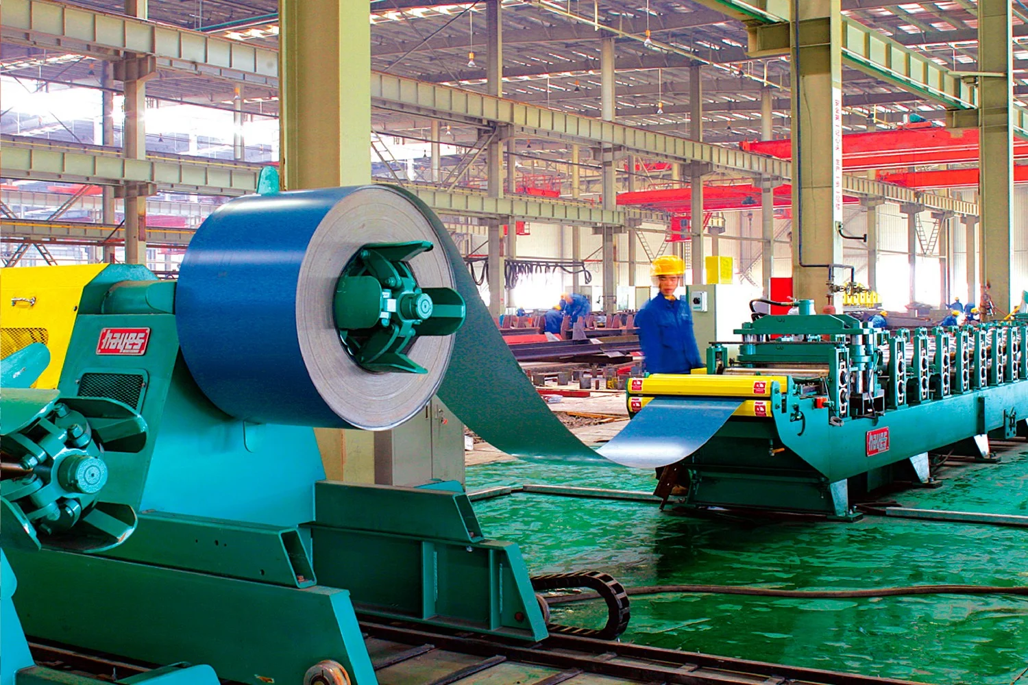
Purlins carry the roof and wall sheeting, but their real job is quieter: they distribute wind, snow and gravity loads into the primary frame at a spacing the cladding can span. Do that with a rolled, punched, shop-cut purlin that arrives at the site ready to bolt — and the frame above your head stops being the bottleneck of the schedule. We cold-form C and Z purlins from Q345 galvanized strip on continuous roll-forming lines, with bolt holes, cut lengths and camber per the shop drawing rather than per the erector's grinder.
What a Cold-Formed Purlin Actually Is
Cold forming bends flat strip at room temperature — no heat, no scale, no distortion. The bend work-hardens the steel at the corners, which is why a cold-formed section is proportionally stronger in service than a hot-rolled one of the same nominal grade.
C and Z purlins are the two standard cold-formed sections for roof and wall framing in portal-frame industrial buildings. The C-section — a channel with inward-turned lips — is the workhorse: it bolts directly to a cleat or a welded bracket, carries sheeting on its flanges, and is the default wherever someone will design and detail it member by member. The Z-section, with its flanges turned in opposite directions, has a different virtue: nest the top flange of one purlin into the bottom flange of the next and you get a continuous, lapped member over the support — the classic way to carry a 9–12 m roof bay without shipping a 12 m length or accepting a moment splice over every rafter.
Both types are roll-formed from strip in our shop from Q235B or Q345B galvanized steel, 1.5–3.0 mm thick, zinc-coated to Z275 (275 g/m² total, both sides). The design bases we work to are GB/T 6725 (chemical composition and mechanical properties of cold-formed steel), AS/NZS 4600 (cold-formed steel structures) and AISI S100 (North American cold-formed steel specification) — the effective-width method, not the gross-section shortcut, is what the section properties in our design reports are computed with. If your project is designed to Eurocode 3 Part 1-3 or GB 50018, we prepare shop drawings and hole schedules to whichever governs your local approval.
What makes a purlin a Permanent purlin rather than a generic mill product is what happens between the coil and the truck: the roll-forming line holds the section dimensions within millimetres, holes are punched in the same pass (so they cannot drift relative to the section), lengths are cut to the shop drawing, and the bundle is tagged to the bay and frame number. On a 10,000 m² roof with 300 purlins, the erector should never have to ask which purlin goes where or elongate a hole to make it fit — that is the entire point of buying purlins from a fabrication line that treats them as engineered members.
Section Nominal Range
- Section height: 140–300 mm
- Flange width: 50–80 mm
- Lip length: 15–20 mm
- Wall thickness: 1.5–3.0 mm
- Strip width: up to 800 mm, forming speed controlled per section
C-Section Dimensions and Theoretical Weights
C-purlins are drilled for cleat connections at the supports and sheeted across the flanges. Hole patterns, end closures and purlin shoes are detailed per bay spacing.
| Section (C h×b×c×t) | Height (mm) | Flange (mm) | Lip (mm) | Thickness (mm) | Weight (kg/m) |
|---|---|---|---|---|---|
| C140×50×15×1.5 | 140 | 50 | 15 | 1.5 | 3.18 |
| C160×60×20×2.0 | 160 | 60 | 20 | 2.0 | 5.02 |
| C180×70×20×2.0 | 180 | 70 | 20 | 2.0 | 5.65 |
| C200×70×20×2.5 | 200 | 70 | 20 | 2.5 | 7.46 |
| C250×75×20×2.5 | 250 | 75 | 20 | 2.5 | 8.64 |
| C300×80×20×3.0 | 300 | 80 | 20 | 3.0 | 11.78 |
Theoretical weight computed on gross section dimensions (perimeter × wall thickness × 7.85 g/cm³) per GB/T 6723 — reference only, actual weight varies with hole punching and bend radii. Intermediate sections and custom hole patterns are formed on request; the roll-forming line is re-tooled per section, so bespoke profiles carry the same tolerance as the catalogue ones.
Z-Section Dimensions and Theoretical Weights
Z-purlins are detailed for lapped continuity: nesting sleeves are shipped per bay, and the overlap length is dimensioned on the shop drawing, not improvised on the roof.
| Section (Z h×b×c×t) | Height (mm) | Flange (mm) | Lip (mm) | Thickness (mm) | Weight (kg/m) |
|---|---|---|---|---|---|
| Z140×50×15×1.5 | 140 | 50 | 15 | 1.5 | 3.18 |
| Z160×60×20×2.0 | 160 | 60 | 20 | 2.0 | 5.02 |
| Z180×70×20×2.0 | 180 | 70 | 20 | 2.0 | 5.65 |
| Z200×70×20×2.5 | 200 | 70 | 20 | 2.5 | 7.46 |
| Z250×75×20×2.5 | 250 | 75 | 20 | 2.5 | 8.64 |
| Z300×80×20×3.0 | 300 | 80 | 20 | 3.0 | 11.78 |
Why Z for long roofs, C for simple ones. A Z-purlin's flanges point in opposite directions, so two lapped purlins nest into one another and the joint behaves as a continuous member over the support — the sagging moment at mid-span and the hogging moment at the support share one cross-section instead of two independent simple spans. A C-purlin on the same 6 m bay must be sized as two simply supported spans, which is a stiffer but heavier and more restrained arrangement. The rule of thumb we recommend is simple: bays up to 6 m and straightforward roofs → C; bays beyond 6 m, wide spans or deep-pitch roofs where uplift governs → Z with lapped continuity. The lapped Z arrangement also answers the largest single problem purlins face in practice — lateral-torsional buckling under wind uplift — because the continuous member over the support is braced at each rafter line by the lap bolts and the anti-sag system.
What the Numbers Guarantee
Five specified properties that turn a purlin from a commodity into a designed member.
High-Strength Strip
Q345B strip with minimum yield strength 345 MPa and minimum tensile strength 470 MPa (GB/T 1591), giving a thinner, lighter purlin for the same load than Q235 grade — with the effective section verified, not assumed, for local buckling.
Hot-Dip Galvanized Z275
275 g/m² zinc (both sides) applied before forming so the coating follows the bends without cracking; salt spray resistance verified per ISO 9227 — no red rust through 1,000 hours on the cut edges and corners that betrayal of thin coil coatings.
Section and Hole Precision
Section height and flange width held to ±0.5 mm, length to ±2 mm, twist within 1°/m — and holes punched in the same forming pass, so the hole pattern cannot drift relative to the section, and every bolt slides home on site.
Lapped Continuous Z Connections
Z-purlins are shipped with nesting lapped joints detailed on the shop drawing: minimum 300 mm overlap at each support, two rows of bolts at each lap, and a splice that transfers the hogging moment instead of resting on the rafter flange.
Controlled Span and Deflection
Simple spans to 6 m, continuous (lapped) spans to 12 m, with service deflection limited to L/200 against gravity and the uplift case checked with the wind load reversed — buckling, not just bending, is what governs a purlin under suction, and we size for it.
Where C & Z Purlins Carry the Load
Industrial Roof Systems
Roof purlins on portal frames, grid structures and pipe-truss buildings — supporting profiled metal sheeting or insulated sandwich panels at 1.2–1.5 m spacing with sag rods and fly bracing designed as one system.
Wall Girts and Cladding Rails
Horizontal wall girts behind metal cladding, composite panels and masonry veneer, sized for the cladding weight, wind suction and the door and window openings that interrupt the grid.
Mezzanine and Floor Joists
Cold-formed joists for mezzanine floors and demountable platforms where the floor live load is modest — 2.0–5.0 kN/m² — and the schedule rewards a joist that bolts in rather than a beam that must be welded.
Canopies and Lean-To Roofs
Single-slope roof framing over loading docks, fuel stations and walkways, where uplifts tend to be violent and the lapped Z at the higher end of the load range earns its weight.
Catwalks, Galleries and Service Platforms
Light access platforms and equipment galleries inside plants, using C-sections as edge beams and joists with the same hole pattern as the rest of the building for fast assembly.
Secondary Bracing Members
Chord bracing, struts and eave elements in portal frames and trusses, detailed with welded gusset or bolted cleat connections that match the primary frame's hole grid.
Purlin Layout Rules That Survive Contact with Site
These are the starting points we use on every scheme — the values our engineers challenge, then confirm, on your actual loads.
Purlin Spacing
Spacing is set by the cladding's spanning capacity, not by the purlin. For profiled steel sheeting, roof purlins at ≤1,500 mm spacing for uninsulated roofs and ≤1,200 mm where insulation increases the cladding self-weight; wall girts at ≤1,200 mm to match standard cladding spans. Sandwich panels with 50–150 mm cores typically allow the same or greater spans, and we verify the actual cladding manufacturer's span table before fixing the grid.
Sag Rods (Tie Rods)
Sag rods turn the collection of individual purlins into a braced assembly and resist the component of the roof load that acts down the slope between frames — an unbraced purlin on a 5° roof carries a notional longitudinal force that drifts every member out of line. Rule: purlin span >4 m gets one line of sag rods at mid-span; span >6 m gets two lines at third points. Rods are M12–M16 threaded bar with turnbuckles, tensioned in a pattern from ridge to eaves so the load path is consistent and re-tensioned after the first year of settlement.
Fly Bracing (Anti-Sag / Knee Bracing at Supports)
At every rafter, the purlin's bottom flange must be prevented from rotating about its longitudinal axis — that rotation is the trigger for lateral-torsional buckling under uplift. Where purlin spans exceed 6 m or the design wind uplift exceeds 0.5 kN/m², we detail 45° fly bracing from the rafter web to the purlin bottom flange at alternate supports, bolted with the same M12 hardware as the sag system so no special tools appear on the roof.
How We Deliver
Every purlin order ships with a layout drawing showing spacing, sag-rod runs, bracing positions and lap lengths dimensioned against the rafter grid — plus a hole schedule that matches the cleats and brackets in the same shipment. The erector's job is to follow the drawing and bolt; the engineer's job — ours or yours — is to have answered the load questions before the coil ever entered the forming line.
Need Purlin Schedules for a Roof or Wall System?
Send us your bay grid, roof pitch, cladding specification and wind/snow loads. We return purlin sizes, spacing, sag-rod and bracing layouts, and a unit-price schedule — with hole patterns and cut lengths in the shop drawings that follow.
Email: market@permanentsteelstructure.com | WhatsApp: +86 18621689980 | Phone: +86 516-83269982