
Tapered Steel Beam — Steel Where Stress Demands It, Not Where Habit Puts It
Tapered beams are not an aesthetic flourish. They follow the bending moment diagram, placing steel only where stress demands it — and a well-designed tapered beam saves 15–25% of steel weight compared with a prismatic beam carrying the same load. That is a saving in material, freight, foundation, and fabrication that repeats on every member of the frame.
Why a Prismatic Beam Carries Steel It Does Not Need
Consider a simply supported beam under uniform load. The bending moment is zero at the supports and reaches its maximum at mid-span; the required section modulus follows the same curve. A prismatic beam — a constant-section member, which is what most fabricators are set up to produce cheaply — must be sized for the worst point and then ships that full section along its entire length, including the zones where the moment is a fraction of the peak. For every metre toward the supports, you are paying for steel that is structurally idle.
In a rigid portal frame the picture is different again but even more favourable to tapering: the maximum bending moments occur at the haunch where the rafter meets the column and at the knee of the frame — not at mid-span. A rafter that is deep at the eaves and shallow at the ridge, and a column that is deep at the base connection and narrow at the top, is the mirror image of the actual stress envelope. The steel is not merely saved; it is relocated to exactly where the structural demand lives.
This is why tapered members are the default choice for engineered portal frames worldwide — and why buying them from a fabricator whose shop cannot cut and weld a taper accurately is a false economy. The taper is the design: if the fabrication drifts, the saved steel stops saving, and the member stops matching its analysis.
How Tapering Works: Following the Bending Moment Envelope
The tapered member is the practical expression of a simple principle: a structure should resist its loads with the least material that is still safe, serviceable, and practical to build.
Web Tapering
The most common and most efficient form of tapering is in the web: the section depth varies along the member while the flange plates stay parallel, usually constant in width and thickness. The web provides shear capacity and, through its depth, the section modulus the bending stresses demand. At the haunch of a portal frame, where the moment is greatest, the web is deepest; toward the ridge, where the moment approaches the pure-bending plateau at the knee region, the web shallows. Because the flanges carry the majority of the bending stress, a deep web near the peak moment and a shallow web elsewhere gives the required capacity with a fraction of the material of a constant-depth section.
Flange Tapering and Hybrid Sections
Where the bending gradient is steep, the flange can also taper or step: a thicker or wider flange at the high-moment end, changing at splice points to a lighter flange. The extreme form is the fully variable section, where depth and flange area both follow the moment envelope — produced when the load case demands the maximum saving, or when the architect's expression requires the taper to be visible. We also fabricate hybrid tapers — Q355B flanges with a Q235B web, for instance — where the grade mix itself follows the stress distribution and buys further economy.
The Engineering Checks That Make Tapering Safe
A tapered member is not a prismatic beam with a fancy outline; it demands its own verification, and a competent fabricator confirms all of the following in the design:
- Lateral-torsional buckling — the critical moment of a tapered rafter is not the prismatic formula; it is judged by the tapered-member buckling theory with the flange loaded in the plane of the web.
- Web shear at the ends — the shallow end of the web must still pass the shear capacity check, including shear-bending interaction where the moment is also high.
- Web stiffeners — where the web is thin relative to depth, intermediate transverse stiffeners are placed at design spacing, and load-bearing stiffeners at concentrated reaction points.
- Tolerance sensitivity — the deeper the taper, the more the section property varies with fabrication error; our fabrication holds the web profile within the tight profile tolerance so the as-built member matches the analysis member.
Tapered Members in Portal Frame Design
The portal frame — the standard structural system for warehouses, factories, and logistics buildings — is where the tapered member shows the largest savings.
In a single-storey portal frame, the governing actions are the bending moments at the two frame knees and the mid-span sagging moments of the rafters. The classic optimized frame therefore uses:
- Tapered rafters — deepest at the haunch, shallowing toward the ridge and the eaves connection, sized so that the section modulus envelope matches the moment envelope;
- Tapered columns — deep at the base (where the fixed-base moment acts) and at the knee, shallow in the middle where the moment drops, avoiding the "banana" shape of a constant column that is mostly idle;
- Haunch segments — a deepened local section at the knee that carries the moment peak without changing the whole rafter;
- Rigid connections — moment-resisting joints whose plate thickness, bolt pattern, and stiffeners are sized to carry the peak moments that make the tapered frame possible.
The optimization is iterative and should be software-driven: the frame analysis, member verification to the governing code (AISC 360, Eurocode 3, or GB 50017), and the cost model trade depth, taper ratio, and grade against each other until the lightest practical frame is found. A taper ratio (depth at deep end divided by depth at shallow end) of 2 to 3 is common; ratios beyond 4 usually hit shear or deflection limits that a second splice better solves. Our structural engineers run this optimization per project rather than reusing a standard frame pattern, because "standard frames" are exactly how the 15–25% saving is squandered on the jobs where the load, snow, and crane geometry are not standard.
Cutting and Welding a Taper That Stays True
Fabricating a tapered beam is not harder than fabricating a prismatic one — but it is different, and the differences are where quality control lives.
CNC Cutting of the Tapered Web
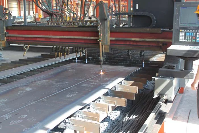
The taper is born in the cutting. On our CNC multi-torch straight-line cutting machines, the web profile is cut from plate with the full taper geometry programmed directly from the shop drawing: starting depth, ending depth, and any intermediate steps are machine-controlled, with cut-edge quality and dimensional accuracy to the millimetre. Two webs from the same billet can be nested flange-to-flange to halve material waste — a detail of shop scheduling that quietly reduces the steel tonnage you pay for.
Cutting the taper correctly is the prerequisite for everything downstream: if the web profile is wrong by a few millimetres, the weld gap against the flange is wrong along the whole member, and the assembled beam deviates from the analysis section by more than the tolerance budget assumed.
Assembly and Welding Sequence Control
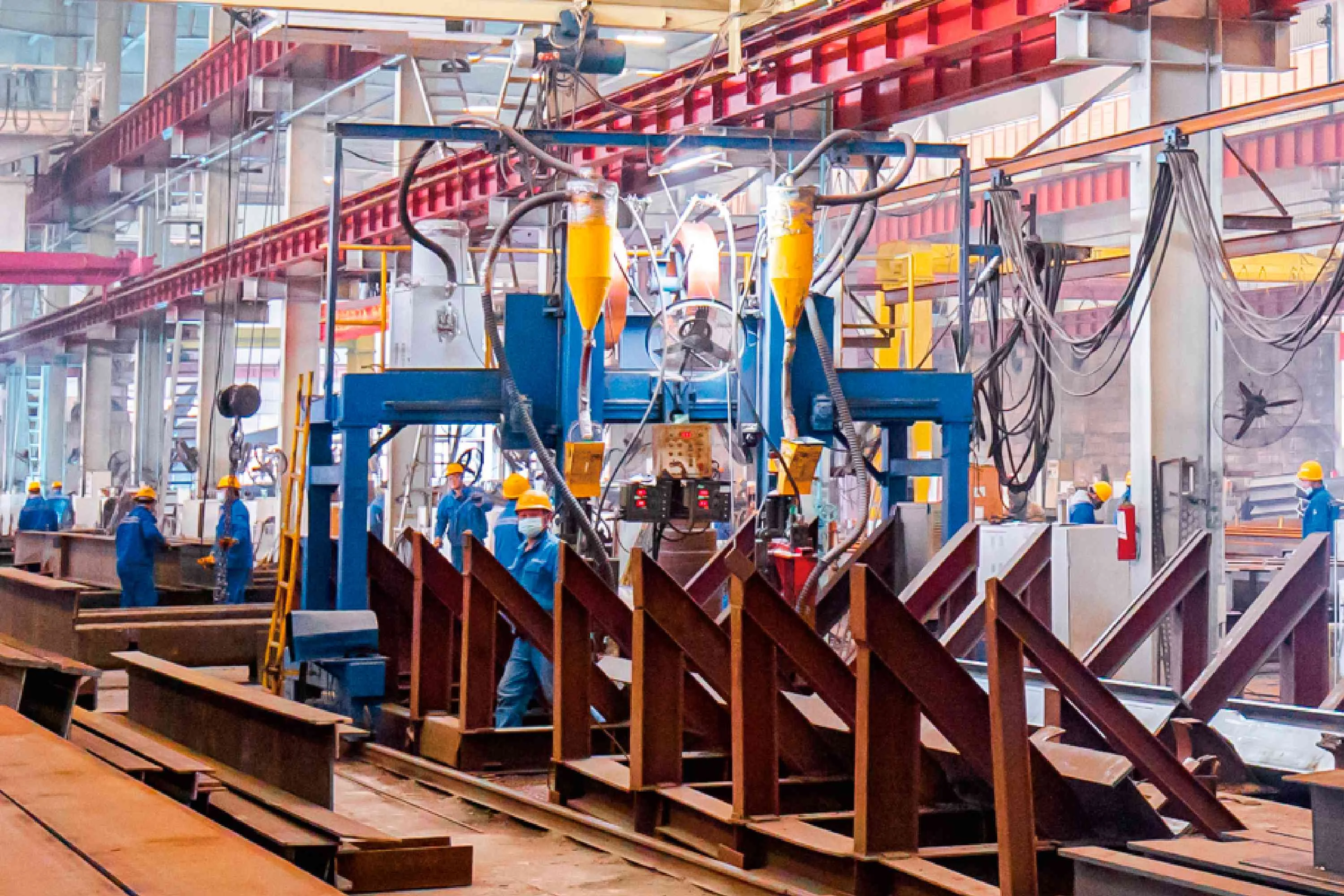
A tapered web meets the flange at a variable angle along the length, so the joint preparation and weld pull must be managed per segment. The taper is a demanding geometry for weld distortion: the weld is longer on the deep side, and the member tends to bow toward the shallow side unless the weld sequence balances the heat input. Our assembly line sets the member on programmable supports and runs the submerged arc welding in a controlled sequence — near and far fillet pairs alternated, heat input matched between the two flanges — then straightens and re-checks the finished member. The geometry you see on site is the geometry the analysis used; that is the entire point of buying a tapered member from a controlled line.
Tapered Member Fabrication Range
- Member length: up to 20,000 mm in one piece
- Section depth: 200–2,000 mm at the deep end
- Taper ratio: up to 4:1 web depth ratio, higher by splice design
- Plate thickness: 6–40 mm, heavier on request
- Profiles: single taper, double taper, stepped, and hybrid-grade sections
What 15–25% Actually Looks Like on a Frame
Lean savings have a habit of looking impressive in a brochure and vague in a quotation. Here is the calculation for a representative portal frame bay.
| Parameter (per 24 m bay, 6 m eaves) | Prismatic Frame | Tapered Frame |
|---|---|---|
| Rafter section | Constant H550×250 | Taper H900→H350 |
| Column section | Constant H450×250 | Taper H700→H300 |
| Frame steel weight estimate | ≈ 6.4 t / bay | ≈ 5.1 t / bay |
| Steel saving | — | ≈ 20% |
| Foundation reaction reduction | Baseline | Lower dead load → smaller footings typical |
| Saving on a 10,000 m² building (40 bays) | — | ≈ 50 t of steel before transport and erection |
The numbers are indicative, not a universal promise — the achievable saving depends on span, eaves height, load, and connection detailing, and on some geometries the taper offers less. What is not negotiable is the direction: on any rigid frame with a real moment distribution, a section that varies with the moment envelope uses less steel than one that does not. We state the range (15–25%) honestly, and the design report we issue with each quotation shows the comparison on your frame, member by member.
The saving compounds beyond the tonnage. Less steel means less freight, a lighter erection crane, fewer welds to inspect, and smaller foundations — on a large logistics building, the foundation saving can rival the steel saving itself, because the foundation columns and pad footings were never oversized for steel they do not need.
Where Tapered Beams Deliver Their Largest Value
Industrial Buildings & Factories
Tapered portal frames for workshops and plants, including frames sized for overhead crane rails where the crane girder demands the deeper, stiffer haunch regions that tapering provides naturally.
Warehouses & Logistics Centres
The classic tapered-frame application: wide clear spans, high bay counts, and a schedule that rewards every tonne removed from the frame. Optimization here is not a refinement, it is the business model.
Commercial & Agricultural Sheds
Long-span clear buildings for retail, sports, and agriculture where a lightweight frame reduces foundation cost on poor soils and speeds erection on any site.
Canopies & Covered Walkways
Single-pitch cantilever and two-pin portal canopies, where the moment envelope is strongly one-sided and a tapered member can remove even more steel than on a symmetrical frame.
From Moment Diagram to Erected Frame
Buying tapered members is a one-way ticket through the supply chain: if the fabricator cannot cut the web to the design slope, cannot control weld distortion along a varying section, and cannot document the as-built profile, then the optimization the designer performed on screen never reaches the site. The 15–25% saving exists only if the fabricated member matches the analysed member.
At Permanent Steel the whole chain is in one building: our structural engineers run the frame optimization and member verification; our detailers issue the shop drawings with the taper geometry embedded; our CNC cutters cut it; our line assembles and welds it; our straightening press and inspectors verify it; and our erectors — where we contract the works — put it up. A tapered frame from us is therefore a single controlled product: the designer's moment envelope, the cutter's geometry, and the erected member are the same thing. If anything in that chain is questionable, it is questioned before despatch, not discovered by the erector.
For an owner or consultant evaluating tapered-frame suppliers, the practical asks are: show the optimization report for a comparable frame (not a generic brochure), confirm the taper tolerance the shop actually holds, and inspect the weld sequence documentation on a sample member. Those three checks will tell you whether you are buying an engineered saving or a painted approximation of one.
As a benchmark for what "holding the taper" means in practice: we routinely verify web depth along the taper to ±3 mm per station, flange squareness within 2 mm, and shop-cut lengths to ±2 mm — measured at the straightening press, recorded on the member's inspection card, and traceable to the shop drawing. A taper that is cut and welded to that discipline behaves in service exactly as the frame model predicted, which is the entire point of the 15–25% weight saving in the first place.
Equally important is knowing where not to taper. Haunch-only and partial-taper frames, symmetrical rafters with haunches at the eaves and apex, and members governed by deflection rather than strength can sometimes be built more economically as prismatic sections with local stiffening — and we will say so in the optimization report rather than selling a taper for its own sake. The optimization study is therefore delivered with its conclusion: the frame configuration that minimizes installed cost (material plus fabrication plus transport plus erection), not merely the one with the thinnest web at the midspan. For long portal frames — typically beyond 30 m clear span — the taper decision also interacts with rafter splices, crane clearances, and delivery lengths, and those trade-offs are resolved in the same report, on paper, before the member is cut.
Tapered Steel Beam Questions from Engineers and Buyers
Is a tapered beam more expensive to fabricate than a prismatic one?
Per tonne, yes — the cutting and welding are more involved. Per frame, usually the opposite, because there are fewer tonnes. The crossover depends on the frame geometry, but for portal frames the total frame cost is typically lower with tapering, which is why the system is the industry standard for engineered industrial buildings.
Can tapered beams be used in multi-span frames and with cranes?
Yes. Multi-span portal frames use tapered rafters between internal columns just as single-span frames do, and crane buildings use tapered columns and rafters with additional checks for the crane load path. The optimization must include the crane actions, which is exactly the kind of frame we analyse per project.
Do you provide the structural design, or only fabrication?
Both. We routinely take a project from concept loads to erected frame — analysis, member design, connection design, shop drawings, fabrication, delivery, and erection supervision. If you have a design already, we fabricate to it and verify the taper geometry against it before production.
What design codes do you verify tapered members against?
AISC 360, Eurocode 3, and GB 50017 are all in our design practice; we run the appropriate tapered-member provisions (e.g., web tapering reduction factors for lateral-torsional buckling) rather than applying prismatic formulas. The verification method is documented in the design report we issue with each quotation.
What information do you need to quote a tapered frame?
Building footprint and bay grid, eaves height and roof pitch, design loads (environs wind/snow, live, any crane duty), foundation conditions if relevant, and the applicable code. We return a frame layout, member schedule, weight comparison, and quotation — the comparison table above is the shape of what you will receive, on your numbers.
Let's Optimize the Steel Out of Your Frame
Send your building geometry and loads. We will run the frame optimization, show you the tapered-versus-prismatic comparison on your own numbers, and quote the lighter frame.
Request Tapered Frame Design & Quote