
Large-Span Grid Structure: 229m Coal Shed Engineering
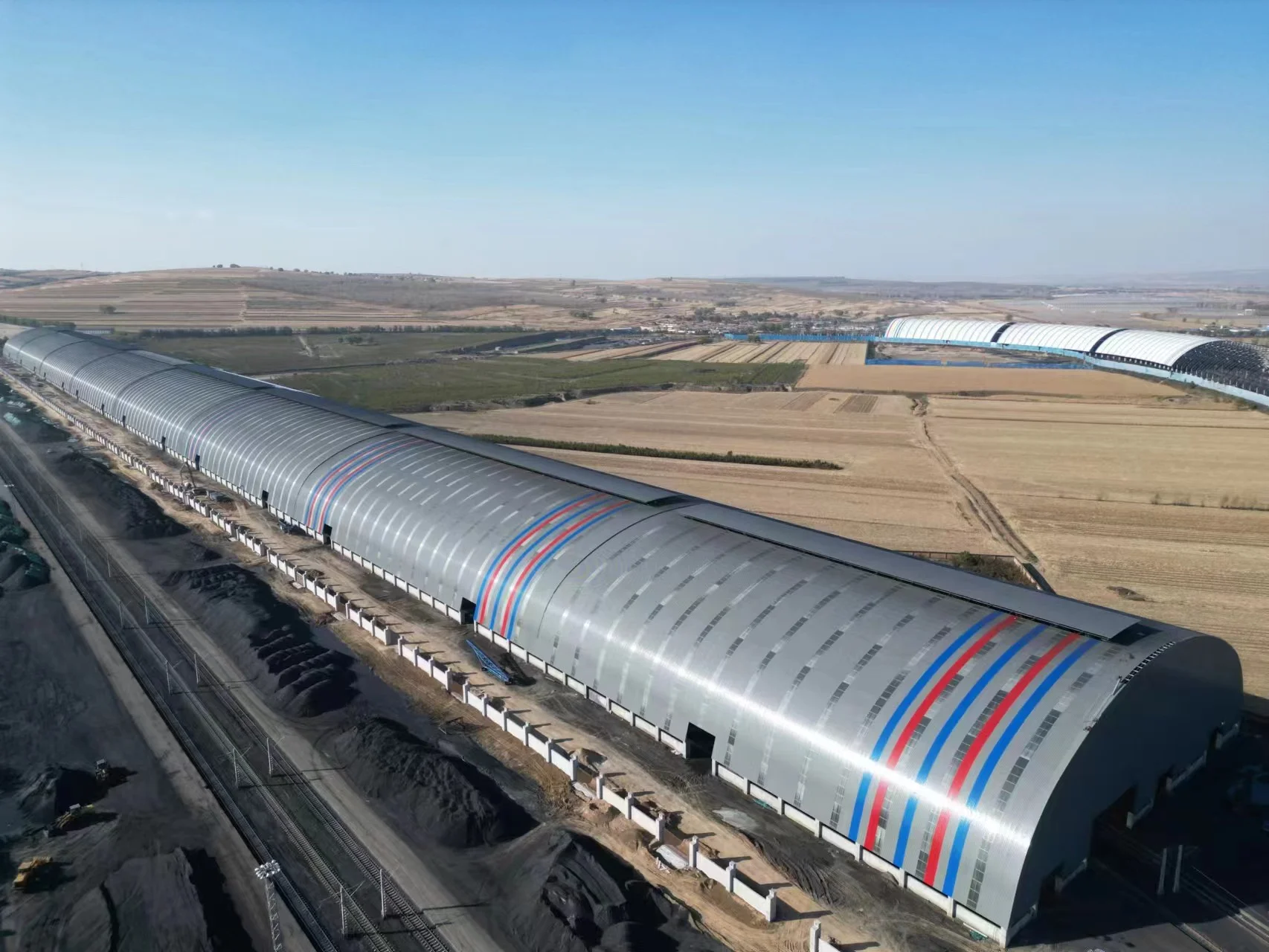
The Guodian Ningxia Fangjiazhuang Power Plant enclosed coal shed spans 229 metres — the world's longest clear span for a coal storage structure. To put this in perspective: 229 metres is the length of two and a half football fields, placed end to end, with no interior columns. The roof must carry snow load, wind load, its own dead weight, and the lateral pressure of coal stockpiled against the lower walls — all without any intermediate support.
This article is an engineering account of how we achieved this record. It is not marketing material. It covers the structural concept (why beam-string, not spatial grid), the pre-tensioning sequence, wind load on a structure with over 40,000 m2 of surface area, foundation anchorage for cable forces, and the construction method. Every number in this article comes from the project's structural analysis and fabrication records.
1. Why Beam-String, Not Spatial Grid?
Our workshops in Xuzhou produce over 3,000,000 m2 of spatial grid construction per year, and the 229 m project below is one of 500+ structures we have delivered since 1999. For most spans up to 120 m, a double-layer spatial grid is the most efficient structure. So why did we not use a spatial grid for the 229 m coal shed?
The answer is weight efficiency at extreme span. A spatial grid structure's weight per square metre increases approximately linearly with span, because the member forces grow with span and the member sizes must increase proportionally. At 229 m span, a double-layer grid would require members with axial forces exceeding 2,500 kN, requiring heavy welded-sphere nodes and large-diameter tubes (Ø273 × 16 mm or larger). The steel consumption would be approximately 85-95 kg/m2, totaling 3,400-3,800 tonnes of steel for the 40,000 m2 roof.
A beam-string structure achieves the same span with approximately 45-55 kg/m2 — a 40-45% reduction in steel weight. The total steel tonnage is 1,800-2,200 tonnes, saving 1,600 tonnes of steel. At 2023 steel prices, this is a material saving of approximately 12-15 million RMB (1.7-2.1 million USD). The saving more than offsets the additional cost of the prestressing cables, cable anchors, and the more complex fabrication and erection process.
The Beam-String Concept
A beam-string structure consists of three components:
- The upper chord (compression member): A steel truss or beam that carries the gravity load in compression and bending. The upper chord is the primary structural member.
- The lower string (tension member): A high-strength steel cable or rod that is tensioned to create an upward force on the upper chord, counteracting the gravity load. The cable works entirely in tension — the most efficient use of high-strength steel.
- Vertical struts (connectors): Vertical members that connect the upper chord and the lower cable, transferring the upward force from the cable to the chord. These struts carry axial compression only.
The structural principle is elegant: the gravity load bends the upper chord downward, and the tensioned cable pulls it back upward through the struts. The cable's tension is pre-calculated to offset a specific percentage of the dead load (typically 70-90%), so that under full dead + live load, the upper chord experiences reduced bending moment compared to a conventional beam. The cable carries the load in pure tension at an efficiency that no compression member can match, because cables do not buckle.
Structural Comparison at 229 m
| Parameter | Spatial Grid (229m) | Beam-String (229m) |
|---|---|---|
| Steel consumption | 85-95 kg/m2 | 45-55 kg/m2 |
| Total steel weight | 3,400-3,800 t | 1,800-2,200 t |
| Maximum member force | 2,500 kN (compression) | 1,200 kN (tension, cable) |
| Cable pre-tension | N/A | 850 kN per cable |
| Deflection under full load | L/250 = 916 mm | L/400 = 573 mm |
| Construction method | Ground assembly + lift | Ground assembly + staged tensioning + lift |
| Foundation load (per support) | 3,200 kN vertical | 1,800 kN vertical + 850 kN horizontal (cable) |
The beam-string is not only lighter but also stiffer (L/400 vs L/250 deflection), because the pre-tensioned cable provides an elastic support along the span that reduces the effective bending length. The trade-off is the horizontal cable force (850 kN per support), which must be anchored in the foundation — a significant additional design consideration discussed in Section 4.
2. The Pre-Tensioning Sequence
The most critical engineering challenge in a beam-string structure is the pre-tensioning sequence. The cable cannot be tensioned in a single operation — the structure's geometry changes as the cable is tensioned, and these geometry changes affect the force distribution in every member. A poorly sequenced tensioning can cause the upper chord to buckle, the struts to overload, or the cable to slack at intermediate stages.
Tensioning in Stages
The coal shed has 7 beam-string units along its length, each spanning 229 m in the transverse direction. Each unit has 5 cables (arranged in a fan pattern from the end anchors), creating 5 tension points per unit. The tensioning sequence for each unit was:
- Stage 1 (10% of design tension, 85 kN): All 5 cables are tensioned simultaneously to 10% of design tension. This removes cable slack and seats the anchorages. The structure is still supported by temporary shoring towers at this stage.
- Stage 2 (30% of design tension, 255 kN): Cables are tensioned to 30%. The upper chord begins to lift off the shoring. Deflection is monitored at 12 points along the span with total station surveying (accuracy ±1 mm). If any point deviates from the predicted deflection by more than 5 mm, tensioning is paused and the structural model is re-checked.
- Stage 3 (60% of design tension, 510 kN): Cables are tensioned to 60%. The temporary shoring towers are removed. The structure now supports its own dead weight through the beam-string action. The deflection at this stage is predicted to be +15 mm upward (camber) at mid-span.
- Stage 4 (85% of design tension, 723 kN): Cables are tensioned to 85%. The structure reaches the pre-load condition, with a mid-span camber of 45 mm upward. This upward deflection is designed to be cancelled by the dead load of the cladding, insulation, and purlins, which are installed after this stage.
- Stage 5 (100% of design tension, 850 kN): Final tensioning to 100% after all dead loads are applied. The structure reaches its design geometry: zero deflection at mid-span under dead load, with the cable providing upward force that offsets 80% of the dead load.
Each stage requires a minimum of 4 hours for force redistribution and creep relaxation before the next stage begins. The total tensioning time per unit is 2-3 days. The 7 units were tensioned sequentially (not simultaneously) to allow monitoring and adjustment.
Force Monitoring During Tensioning
Every cable is instrumented with a load cell (vibrating wire strain gauge type) at the anchorage, providing real-time tension readings during the tensioning sequence. Additionally, the upper chord is instrumented with strain gauges at 8 locations per unit, monitoring the stress redistribution. The monitoring data is compared to the structural analysis model in real-time, and any deviation exceeding 10% triggers a pause for investigation. During the actual tensioning, the maximum deviation from the predicted forces was 6% — well within the 10% tolerance.
3. Wind Load on a 229-Metre Span Structure
The coal shed's roof area is approximately 40,000 m2 (229 m × 175 m). This enormous surface area presents a significant wind load challenge. The structure is located in Ningxia, an inland region with a basic wind pressure of 0.45 kN/m2 (50-year return period, per GB 50009).
Wind Load Calculation
The wind pressure on the roof depends on the roof shape factor (Cp), which varies with position. For a curved (arched) roof with a rise-to-span ratio of 1/6, the wind pressure coefficients per GB 50009 are:
- Windward quarter: Cp = −0.2 (uplift, moderate)
- Crown (top): Cp = −0.8 (uplift, high)
- Leeward quarter: Cp = −0.5 (uplift, moderate)
- Windward wall: Cp = +0.6 (pressure)
- Leeward wall: Cp = −0.3 (suction)
The total uplift force on the roof under design wind (0.45 kN/m2 basic pressure, with height and terrain factors increasing this to 0.68 kN/m2 at the eave height of 45 m):
Fuplift = 0.68 × (−0.8) × 40,000 m2 = −21,760 kN (uplift)
This uplift force of 21,760 kN must be resisted by the structure's dead weight and by the foundation tie-down. The dead weight of the roof structure (1,800 tonnes) provides 17,640 kN of gravity resistance. The remaining 4,120 kN of uplift must be resisted by the foundation anchors — which must also resist the 850 kN horizontal cable force per support. The combined vertical and horizontal loads make the foundation design a critical component of the project.
Wind Tunnel Testing
For a structure of this scale and importance, we supplemented the code-based wind load calculation with wind tunnel testing at Tongji University's boundary-layer wind tunnel. A 1:200 scale model was tested in both the along-wind and cross-wind directions, with pressure taps at 120 locations on the roof surface. The wind tunnel results confirmed the code-based coefficients within 10%, with two notable exceptions:
- Corner zones: The wind tunnel showed localized uplift coefficients of −1.2 at the roof corners (vs code value of −0.8), due to vortex formation. We reinforced the corner connections and increased the dead load (concrete ballast) at these locations.
- Cross-wind response: The cross-wind direction (perpendicular to the 229 m span) showed a dynamic response from vortex shedding, with a resonant frequency of 0.8 Hz. The structure's natural frequency is 1.2 Hz, which is sufficiently different from the vortex shedding frequency to avoid lock-in, but we added tuned mass dampers (TMD) at the crown to mitigate any resonant amplification.
4. Foundation Anchorage for Cable Forces
The beam-string structure transfers two forces to each foundation: a vertical load (1,800 kN downward under dead + live, or 520 kN upward under wind uplift) and a horizontal load (850 kN outward from the cable tension). The horizontal force is the defining design challenge for the foundation.
Foundation Type Selection
The site is on alluvial soil with a bearing capacity of 180 kPa (medium-dense gravelly sand). Three foundation options were evaluated:
- Shallow raft foundation: Resisted by soil friction on the raft underside. The required raft area to resist 850 kN horizontal force (with a soil friction coefficient of 0.35) is 850 / (0.35 × 180) = 13.5 m2 — achievable, but the uplift case (520 kN) requires the raft weight to exceed 520 kN, requiring 53 m3 of concrete. The raft would be 6 m × 3 m × 3 m deep — large but feasible.
- Driven piles: Batter piles (inclined at 15°) can resist both vertical and horizontal loads. 4 Ø600 mm piles per support, with a vertical capacity of 1,200 kN and a horizontal capacity of 350 kN each, provide a total horizontal capacity of 1,400 kN — 65% above the 850 kN demand. This was the selected option because the piles also resist the uplift case through skin friction (200 kN per pile).
- Rock anchors: Not feasible because the site is alluvial soil with bedrock at 25 m depth.
Pile-to-Structure Connection
The pile cap is a reinforced concrete block (3.5 m × 3.5 m × 1.5 m deep) that transfers the cable tension force to the batter piles through a reinforced concrete strut-and-tie system. The cable anchorage is a cast-steel anchor block embedded in the pile cap, designed to transfer 850 kN of tension to the concrete through bond and bearing. The anchor block is designed per GB 50010 (concrete structural code) with a minimum development length of 1.2 m for the cable anchor bars (Ø75 mm, 40Cr steel).
5. Construction Method: Ground Assembly and Synchronized Lift
The coal shed's construction method was dictated by two constraints: the 229 m span (too large for crane-based assembly at height) and the pre-tensioning requirement (cables must be tensioned from the ground before the structure is lifted into final position).
Step 1: Ground Assembly
The 7 beam-string units were assembled at ground level in a laydown area adjacent to the coal shed site. Each unit was assembled on temporary supports (scaffold towers) that positioned the upper chord at 1.5 m above grade — sufficient for workers to access the underside for bolt installation and cable threading. The units were assembled in sequence, with each unit's assembly taking 8-10 days (4-person crew per unit, using bolted connections for the truss members and cable anchor blocks).
Step 2: Cable Installation and Initial Tensioning
Cables were threaded through the strut connections and anchored at both ends. Stages 1-3 of the pre-tensioning sequence (10%, 30%, 60%) were completed at ground level, with the structure still supported on scaffold towers. This allowed verification of the force distribution and geometry before the lift — a critical risk management step, because any problem found after the lift would be extremely difficult and expensive to correct at 45 m height.
Step 3: Synchronized Lift
The lift used a synchronized hydraulic jacking system with 4 jacking points per unit (at the quarter points of the 229 m span). Each jack had a capacity of 2,500 kN and was computer-controlled to maintain synchronization within ±5 mm of vertical displacement across all points. The total lift load per unit was approximately 6,800 kN (the weight of the steel structure plus the partially tensioned cables).
The lift rate was 0.5 m per hour — deliberately slow to allow continuous monitoring of force distribution, cable tension, and structural geometry. At each 5 m increment, the lift was paused for a complete survey and force check. The total lift from ground level to final position (eave height of 18 m, crown height of 45 m) took approximately 50 hours per unit.
Step 4: Connection to Foundations and Final Tensioning
Once the unit was at final elevation, the end connections were bolted to the pile cap anchor blocks. Stages 4 and 5 of the pre-tensioning (85% and 100%) were then completed with the structure in its final position. The temporary shoring towers were removed after Stage 5, and the structure was self-supporting.
Step 5: Cladding and Purlin Installation
Purlins and cladding were installed after the structure was self-supporting and the cable tensioning was complete. The dead load of the purlins and cladding (approximately 0.25 kN/m2) was applied symmetrically to avoid unbalanced loading on the beam-string system.

6. Structural Analysis and Verification
The structural analysis of the 229 m beam-string structure was performed using nonlinear finite element analysis (FEA) with geometric nonlinearity (P-Δ effects and cable sag). The analysis model included:
- 1,847 beam elements for the upper chord truss members, with elastic-plastic material models for Q355B steel.
- 35 cable elements (5 per unit × 7 units) with tension-only behaviour and an initial pre-tension of 850 kN.
- 140 truss elements for the vertical struts, with compression-only behaviour.
- Nonlinear boundary conditions at the foundations, modelling the pile stiffness in both vertical and horizontal directions.
The analysis verified:
- Strength: Maximum member stress under all load combinations (dead, live, wind, snow, temperature) is 285 MPa — 81% of Q355B yield strength (355 MPa), with a safety factor of 1.25.
- Stability: The upper chord's elastic critical load is 2.8 times the design load, exceeding the GB 50017 minimum of 2.0 for primary structures.
- Serviceability: Maximum deflection under full dead + live load is 573 mm (L/400), well within the GB 50017 limit of L/250 (916 mm) for roof structures.
- Cable fatigue: The cable stress range under wind loading is 45 MPa, which is below the fatigue limit of 70 MPa for high-st steel cables (per GB/T 18306), providing a service life exceeding 2 million cycles.
7. Why This Project Matters
The 229 m coal shed is not merely a record. It demonstrates three engineering principles that apply to any large-span steel structure project:
First, structural system selection should be span-driven, not preference-driven. We fabricate more spatial grids than any other structure type (over 3,000,000 m2 per year), but we did not use a spatial grid for this project because it was not the right structure at this span. The beam-string system saved 1,600 tonnes of steel and produced a stiffer, more efficient structure. The right structure for your project depends on your span, load, and site — not on what your manufacturer prefers to build.
Second, pre-tensioning is an engineering discipline, not a construction task. The 5-stage tensioning sequence, with real-time force monitoring and geometric verification, took 2-3 days per unit and required a dedicated engineering team on site. Skipping or accelerating this process would compromise the structure's force distribution and potentially cause failure.
Third, extreme span requires extreme verification. Wind tunnel testing, nonlinear FEA, strain gauge monitoring, and synchronized lifting systems are not luxuries — they are the engineering rigor that makes a 229 m span possible and reliable. The cost of this verification is approximately 3-5% of the total project cost; the cost of a failure at 229 m span is immeasurable.
For more on our beam-string structural system, visit our beam-string structures product page. For the full project details, see the Ningxia coal shed project page. To learn about spatial grid structures for spans where they are the right choice, visit our bolted sphere grid product page.
Conclusion
The 229 m beam-string coal shed represents the intersection of structural innovation, manufacturing capability, and construction discipline. It is not the longest span we have built (our portfolio includes bridges and infrastructure projects at greater spans), but it is the longest clear-span roof structure, and the engineering challenges it presented — pre-tensioning, wind load, foundation anchorage, synchronized lifting — are applicable to any large-span steel structure project.
If your project requires a large-span steel structure — whether it is a coal shed, a sports arena, an aircraft hangar, or an industrial facility — the choice of structural system is the first and most important decision. We can engineer spatial grids for spans up to 120 m, beam-string systems for spans from 60 to 250 m, and hybrid systems that combine the advantages of both. Contact our engineering team with your span, load, and site requirements, and we will recommend the system that is right for your project — not the system we prefer to build.
Need Expert Engineering for Your Steel Structure Project?
Our engineers bring 25+ years of experience and hold the Special-Class qualification for spatial grid structure manufacturing — the highest tier in China. From 30-metre workshops to 229-metre world-record spans, we engineer the right structure for your project. Send us your drawings or concept requirements today.
Request a Consultation