
Guodian Ningxia Fangjiazhuang Power Plant Enclosed Coal Shed
A 229 m clear-span prestressed beam-string arch truss — the longest-span steel structure of its kind in the world at completion — enclosing approximately 4,000 tonnes of permanent steelwork. Designed, fabricated, erected and delivered EPC by Jiangsu Permanent Steel Structure Co., Ltd.
| Project Type | Enclosed power-plant coal storage shed |
|---|---|
| Location | Ningxia, China |
| Structural System | Prestressed beam-string arch truss with high-strength lower-chord cables |
| Key Dimensions | 229 m clear span; designed to operate stacker-reclaimer equipment without interior columns |
| Steel Quantity | Approx. 4,000 tonnes of permanent steelwork |
| Supply Scope | Design, fabrication, supply and erection/EPC delivery as described in the case study |
| Design Basis | Bulk-storage enclosure, wind and cable-stability checks, foundation thrust control and environmental dust containment requirements |
| Installation / Logistics | Prestressing sequence, abutment thrust control and staged erection; detailed schedule available on request |
| Client / Completion Year | Available on request; public project identity shown without unsupported client claims |
Need exact tonnage, installation schedule, crane plan or container count for a comparable project? Request a technical quote and send your drawings or sketch.
The longest-span steel structure ever built for bulk-material storage
At the Guodian Ningxia Fangjiazhuang power plant, Permanent Steel delivered what was, at completion, the longest-span steel structure for enclosed bulk-material storage anywhere in the world: a coal shed with a clear span of 229 metres. The span is not a decoration. It is the minimum structurally honest answer to a question of geometry, machinery and regulation — how do you enclose a coal storage yard that must feed a large thermal power unit, operate stacker-reclaimers that sweep the entire stockpile, and comply with air-quality rules that no longer permit coal to sit in the open?
The structural system chosen to cross that span is the prestressed beam-string arch truss: an arch-shaped spatial truss whose lower chord is replaced — in the regions where tension dominates — by high-strength prestressed cables interacting with the arch rib through vertical struts. The cables do not merely brace the arch; they pre-compress it, counter its self-weight, control its horizontal thrust at the abutments and tune its live-load response. Prestressing is what made 229 m possible without the member sizes, foundation reactions and fabrication weight that a passive structure of the same span would have demanded.
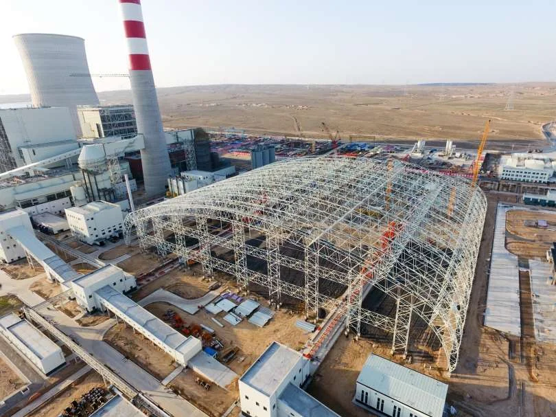
This case study documents why the span exists, how the beam-string system works, where the 4,000 tonnes of steel went, how the prestress was engineered and applied, and how the world record was won with the discipline of a production project rather than the drama of a stunt. It is the flagship of Permanent Steel’s long-span portfolio and the reference point against which we measure every later span — including our own 220 m prestressed truss project at the Shentou power generation units in Shanxi, described in a companion case study.
Why a coal shed must be 229 metres wide
No client asks for a 229-metre span out of ambition. They ask because the alternative — a narrower shed with interior columns — fails on four hard grounds.
1. The stockpile and the machinery that must cover it
A large thermal power unit burns on the order of 1.5–2 million tonnes of coal per year, and a storage yard sized for meaningful strategic reserve and procurement flexibility is measured in hundreds of thousands of tonnes. That inventory forms a stockpile whose width and height are dictated by conveyor geometry and reclaim strategy. The reclaim system is typically a stacker-reclaimer on rails — a machine with a boom reach of tens of metres that must sweep the entire footprint of the pile to deliver fuel to the plant bunkers. Every square metre the machine cannot reach is coal that must be reclaimed by smaller, slower equipment or by dozers zoned around the rails. Columns inside the envelope would riddle the reclaim machine’s travel corridor and blind spots into its path — an operational impossibility at a plant whose fuel supply cannot be interrupted.
2. Environmental regulation changed the rules
Air-quality compliance under Chinese environmental law requires thermal power plants to store bulk coal in enclosed facilities — wind-borne coal dust from open yards is a measurable fugitive-emission problem, and regulatory enforcement has made open storage progressively untenable. Enclosure must cover the stockpile, the reclaim rails, the transfer towers and the yard-crane envelope. Once the enclosure must span the reclaim machine’s full travel width plus the pile’s clearance zones, the building envelope is already at the scale of a very large span — and the cost equation flips: beyond roughly 60–80 m of clear width, a grid roof or arch system with no interior columns becomes cheaper and faster to build than a forest of internal columns plus their local enclosures, foundations and dust-control headaches.
3. Stacking height drives height; span drives economy
The shed height is set by the reclaim boom and the pile’s natural repose angle — typically 35–40 degrees for thermal coal. The width is set by inventory and machine travel. Both are dictated by physics and operations, not by architecture. Given a target clear interior width of roughly 220 m for the yard envelope, the shed either spans it with one structural system or with a sequence of narrower vaults interrupted by internal supports. The latter multiplies foundation, membrane, drainage and maintenance lines and re-introduces the machine-obstruction problem. A single continous span is not luxury; it is the low-total-cost solution.
4. The record was a boundary of capability, not a marketing target
Engineers on both sides of the table understood that crossing 229 m with a passive arch or truss would have required either absurdly heavy members or unacceptable deflection. The beam-string system with prestressing existed precisely to break that deadlock — it had already demonstrated viability at spans approaching 200 m elsewhere, and the project team’s job was to take the system into the 220 m+ class with complete analytical honesty. The world-record status was a by-product of solving the client’s problem correctly; it was not the design objective. That distinction matters, because it is the difference between a structure built for a photograph and a structure built to earn coal for twenty years.
The prestressed beam-string arch truss, dissected
A conventional arch truss of 229 m span would be a study in extremes: a deep compression rib whose weight dominates every load combination, hinge-like supports that must swallow enormous horizontal thrust, and a structure whose dead load is so large that live loads barely matter. The beam-string system re-engineers that balance.
Anatomy of the system
The roof envelope is a series of transverse arch-truss ribs spaced along the shed’s length, each rib carrying roof purlin and cladding systems, with longitudinal bracing and wind-stability systems between ribs. Each rib has three cooperating families of members:
- The arch truss (the body): an upper arched truss — two parallel chord planes braced as a spatial truss — whose curvature converts downward load into axial compression. In its own plane it behaves as a deep beam arched over the span.
- The struts (the skeleton): intermediate vertical or near-vertical members connecting the arch rib to the cable below, at intervals of several metres along the span. The struts are in compression; they are the levers through which cable force acts on the arch.
- The prestressed cable (the muscle): a high-strength steel cable or strand system running below the rib, anchored at the two abutments, passing through the strut feet. When tensioned, the cable pulls inward on the struts’ feet and downward on the rib crown, creating an upward reaction system that counteracts the arch’s self-weight exactly where it hurts most — at mid-span.
Why it beats a passive arch at this scale
- Dead-load counteraction: the prestress induces a force state in the rib that opposes the gravity bending of self-weight, effectively subtracting a large, predictable load from the member design envelope. The rib can be proportioned for live-load and stability demand instead of being crushed by its own weight.
- Thrust control at the supports: an un-tensioned arch thrusts horizontally into its abutments; a low arch of 229 m with shallow curvature develops enormous thrust, driving foundation cost and creating soil/structure interaction problems. The beam-string’s cable carries the tension line between abutments — a self-balanced system — so the foundation bears predominantly vertical load. On a power-plant site where the shed abuts yard hardstanding, conveyor foundations and buried services, this self-balancing property is worth real money and real risk reduction.
- Stiffness upgrade: the tensioned cable stiffens the whole assembly against asymmetric load, making the system’s deformed shape stiffer, its natural frequencies higher, and its wind response calmer than a comparable passive arch.
The result is a system whose effective resource is prestress rather than mass: the structure carries a 229 m span with roughly 4,000 tonnes of main steelwork, a figure that a passive-system designer of the same span would find hard to approach with the same deflection and thrust performance.
Engineering the tension: analysis, sizing and the tensioning sequence
Prestress is a stored load. Getting it right — and proving it on site — is the heart of a beam-string project, and the discipline is different in kind from ordinary steel design.
Analysis that takes the cable seriously
The structure was analysed with geometric and material nonlinearity from the first day, because cable action is inherently nonlinear: cable sag, cable elongation, strut shortening, rib shortening and temperature all interact with the prestress level, and the deformed geometry of the final structure differs measurably from the un-tensioned geometry. The working basis was a full three-dimensional finite-element model in which every rib, strut, cable and brace participated, with:
- Two-stage analysis: Stage 1 — the structure under dead load plus the prescribed prestress force, establishing the deformed geometry and member forces at “state of equilibrium after tensioning”; Stage 2 — all subsequent load cases (live, coal-pile asymmetric load, wind, snow, temperature, seismic) applied to the pre-stressed state.
- Asymmetric live load: the deadliest case for a long-span arch is not uniform load but the partial load of an asymmetric stockpile — coal piled high on one side, empty on the other — combined with wind. Every intermediate filling condition was enveloped, because the shed spends its life in partial fill, not in the neat full-symmetry state textbooks draw.
- Stability with geometric imperfection: global and member-level stability were verified against the code imperfection envelopes for grid structures of this class, with the prestress state included as part of the stiffness reference.
- Temperature: a shed of this scale experiences large thermal swings between winter and summer and, in Ningxia, between day and night; cable force and rib stress were enveloped across the seasonal and diurnal temperature range, and movement provisions were placed accordingly.
The tensioning sequence
Prestress is never simply “applied”; it is staged and verified. On this project the cable systems were tensioned in a defined sequence from the abutments toward the crown zone, strand by strand in the multi-strand anchorages, using calibrated jacks with simultaneous control of jack force and strand elongation. The acceptance criteria were dual — force and elongation must both land inside their envelopes — because elongated-but-undertensioned strands and tensioned-but-underelongated strands are each failures of a different kind. After tensioning, cable force was further verified by the frequency (vibration) method on sampled strands: the measured natural frequency of the free cable length yields the tension directly, an independent cross-check on the jack readings.
The sequence was staged so that each rib reached its completed prestress state while the adjacent ribs and the longitudinal bracing could absorb the redundant force redistributions — on a beam-string shed, tensioning one rib changes its neighbours’ state slightly, and the model predicted exactly how much. The survey verification of the crown line after tensioning matched the predicted deformed geometry within the specified tolerance, which is the moment a beam-string structure proves itself: the steel does what the model says, the crown rises by the computed value, and the “record span” becomes a measured, documented fact rather than a headline.
Where 4,000 tonnes of steel went, and how it was made to work
Approximately 4,000 tonnes of structural steelwork supports this roof system — a figure that deserves unpacking, because the novelty of the system does not reduce the scale of the material choreography.
Member population
- Arch-truss chords: the top- and bottom-chord members of each rib, fabricated from structural hollow sections and plate in high-strength Q345–Q420-grade families, sized by the axial force envelope of the prestressed state. Chord sizes taper from the heavy quarters (compression and bending dominated, near the abutments and crown) to the lighter mid regions.
- Web members and braces: the diagonal and vertical lattice of each rib plus the longitudinal wind-bracing systems between ribs — the population that gives the shed its three-dimensional stiffness against non-uniform wind and earthquake.
- Struts and cable hardware: the prestress struts, their bases with the strand deviators, the anchorage assemblies at the abutments, and the strand systems themselves — high-strength, low-relaxation material with certified breaking loads several times the working force.
- Secondary steel: purlin systems, roof bracing, cable walkways, inspection platforms and the connection steel that ties the envelope to the ribs.
Fabrication at the limit of tolerance
Every member of every rib was fabricated at Permanent Steel’s Xuzhou base and pre-machined with the camber and geometry compensation that the two-stage analysis prescribed. The critical discipline at this scale is geometry transfer: the model’s node coordinates, including the predicted post-tensioning displacements, were written directly into the fabrication drawings so that the as-built rib geometry after tensioning lands on the design surface rather than beside it. Trial assembly of representative rib segments — including the abutment joints where cable anchorage forces concentrate — was performed on a surveyed floor before mass production, closing the loop on fit between the truss chords, the struts and the cable hardware.
Welding, NDT and traceability
Welding on thick high-strength plate and heavy hollow sections requires procedure qualification for every joint class, controlled preheat, and inspection proportionate to consequence: full-penetration butt welds at chord splices and anchorage zones were verified by 100% ultrasonic testing; fillet and partial-penetration welds were sampled at rates above the code minimums with MPI where surface-critical. Each member’s heat number, mechanical test certificate, weld procedure and inspector’s sign-off travelled with its coded identity from the Xuzhou workshop to the site register — not because the client asked for a beautiful document, but because a 229 m arch has no room for a member whose pedigree is unknown.
The self-balanced force loop and what it does for the foundations
A passive 229 m arch pushes outward on its supports with a horizontal thrust measured in thousands of tonnes. That thrust must be resisted — by massive abutments, by endless ties, by pile groups designed for uplift and drag — and the cost of resisting it invisible in the roof photograph. The beam-string system closes the force loop instead: the tensioned cable runs between the two abutments, so the horizontal component of the arch’s action is carried inside the structure itself, and the foundation experience is predominantly vertical load.
That property was not decorative on this site. The shed sits within a working power-plant yard where the ground under and around it carries buried services, drains, conveyor tunnels and hard-standing; a structure that demanded broad structural abutments and deep tie systems would have collided with everything the yard needed to keep doing. With the self-balanced system, the foundation scheme was concentrated, predictable and cooperative with the site’s existing infrastructure — a design benefit expressed in metres of dug earth, tonnes of concrete and weeks of programme.
The abutment details themselves carried the discipline inward: the cable anchorage zones were designed as bearings tolerant of the multiple force directions the prestress programme applies, verified by NDT, and detailed so that the anchorages remain inspectable for the life of the shed. Every hot-spot at the ends of a self-balanced system is hidden in plain sight — deliberately designed, deliberately inspected, deliberately documented.
Erecting a 229 m arch: sequence, lifting, closure and tensioning
No crane in the world lifts a 229 m arch as a single piece, so the structure was assembled from the ground up, in a sequence that kept every intermediate state stable and verifiable.
Ground assembly and block lifting
Rib segments were assembled at ground level on purpose-built jigs — where welders work at bench height, inspection is accessible, and fit-up tolerances are checked against the surveyed jig before any permanent welding. Completed segments were then lifted by heavy crawler cranes onto temporary support towers placed along the span, docked, aligned and connected. Temporary towers were staged so that each new segment’s weight, plus the wind load on the partially erected ribs, was fully accounted in the erection scheme — with temporary guys and plan bracing detailed in the drawings, not improvised in the field.
The closure segment
The final segment — the crown closure — was dimensionally verified against the two sides’ accumulated geometry before cutting. Closure on a 229 m arch is the moment where every fabrication tolerance, every lift settlement and every thermal displacement of the day expresses itself in a single joint; the procedure therefore specified the acceptable gap window, the time-of-day targeting for temperature stability, and the sequence of stitch-welding to closure. It was executed once, correctly, which is what happens when the closure geometry is analysed as carefully as the service load cases.
Tensioning as the final erection step
After the full rib set was self-stable, the prestress programme ran in the staged sequence described above — abutment-to-crown across the rib population, with dual force-and-elongation control. The final evidence of success was not a jack gauge but the survey: the crown line settling onto the design surface, the cable forces confirming the model, and a 229 m structure standing with its own internal tension balance — no external tie-downs, no visible props, no residual wherewithal. The enclosure and cladding followed, converting the skeleton into the dust-tight, weather-tight storage envelope the plant operates today.
How the 229 m span relates to the structures that came before and beside it
Record claims are only meaningful against a defined category, and the honest catalogue of this one is precise: at completion, the Ningxia shed was the longest-span steel structure for enclosed bulk-material storage (coal shed) in the world, and one of the longest clear spans of any building type achieved with a prestressed arch structural system.
The generations before it
Enclosed coal storage at this scale is a young discipline. Early large coal sheds in China and abroad were enclosures in the 100–180 m class, built with cylindrical shell grids, space grids and conventional arch trusses — typified by projects such as our own 118 m-span, 1,000 m-long cylindrical shell grid at Huizhou Port, which remains one of the world’s most extended coal enclosures. The step from ~180 m to 229 m is not incremental in engineering terms: it is the boundary where passive systems begin to be crushed by their own weight, member sizes become unshippable, and the economics of prestress finally win outright. The beam-string arch truss — developed and refined in Chinese spatial-structure practice — was the technology designed for exactly that boundary, and Ningxia is its world-span proof point.
The systems beside it
Each long-span application chooses among a short list of systems, and the differences matter:
- Beam-string arch truss (this project, 229 m): prestress-controlled thrust, self-balanced cable line, best choice where foundation reactions matter and span is extreme.
- Prestressed truss (our Shanxi project, 220 m): a planar truss with induced prestress — shallower build height, different erection logic, chosen where the site and foundation conditions favour a flatter profile. See Shanxi Zhongdian Shentou power generation unit study.
- Cylindrical shell grid (our Huizhou project, 118 m): a two-way grid vault, ideal at medium spans where 1 km of continuous enclosure, expansion joints and typhoon-wind economy dominate the brief.
- Cable-net and membrane systems: lighter, but with durability and fire-safety profiles that thermal-power operators have been reluctant to accept over coal.
What the record changed
The Ningxia shed demonstrated that 220 m+ spans are deliverable at production-standard quality, with conventional fabrication plant, standard site equipment and verifiable prestress. It moved the boundary of the feasible for thermal-power, logistics and port operators across the industry — and it is the reference against which Permanent Steel’s long-span team quotes every subsequent bulk-storage project: show us the span, we will show you the system that crosses it.
Performance evidence: monitoring, survey and continued service
A record span earns credibility through measurement, and this project was instrumented and verified on three levels.
- Construction-stage verification: every tensioning stage was documented with jack force and elongation; sampled cable strands were verified by frequency-method tension measurement; and crown-line survey after tensioning confirmed the predicted deformed geometry.
- Commissioning and early-load verification: the shed was operated through partial-fill states while the structure was surveyed again — the asymmetric-stockpile case that dominated the analysis was examined live, against model prediction, and found to match within the specified margins.
- Continued service record: the enclosure has since served its power-generation duty through multiple annual cycles — hot summers, the severe cold and wind of Ningxia winters, repeated asymmetric filling and reclaiming — without structural incident, with the cable system exhibiting stable tension and the connections free of distress at inspection.
That record is the reason the 229 m span is presented in this portfolio as engineering evidence rather than as a trophy: it was built to be measured, and it measures true.
Long-span systems and adjacent projects
This project is the flagship of Permanent Steel’s long-span and bulk-storage capability. The pages below document the systems and the companion projects that complete the picture:
- Shanxi 220 m prestressed truss — a different system crossing nearly the same span.
- Huizhou Port 118 m × 1,000 m coal yard — the medium-span, extreme-length cylindrical shell grid lineage.
- Spatial grid structures — the joint and grid technology family behind our large-span roofs.
- Metal roof and envelope — the cladding systems that close the envelope.
- EPC engineering and erection services — the single-accountability delivery model this project ran on.
Have a bulk-storage span no one else will quote?
Send us your stockpile plan, reclaim machinery envelope and site constraints. Our long-span engineering team will respond within 48 hours with a system recommendation — and a structural quotation, not a square-metre guess.
Email the Long-Span Team WhatsApp Our Engineer WhatsApp: +86 18621689980
Or call +86 516-83269982 and ask for the long-span engineering team.