
Guangdong Huizhou Port Quanwan Terminal Enclosed Coal Yard
A 1,000-metre-long, 118 m-maximum-span silkworm-cocoon-shaped three-center cylindrical shell grid — approximately 7,000 tonnes of steel, bolted-and-welded composite sphere joints, bottom-chord support — engineered, fabricated and erected by Jiangsu Permanent Steel Structure Co., Ltd.
A kilometre of coal enclosure in one continuous shell
The Quanwan terminal of Huizhou Port, on Guangdong’s coast, receives coal by sea for the power and industrial demand of the Pearl River Delta. The coal yard feeding the terminal’s storage and transshipment operation is enclosed by one of the longest continuous steel enclosures ever built for bulk-material storage: a cylindrical shell grid 1,000 metres long with a maximum clear span of 118 metres, carrying approximately 7,000 tonnes of structural steelwork.
Unusually, the enclosure’s cross-section is not a semicircle. It is a silkworm-cocoon profile — a three-center circular-arc form in which a flatter crown arc is joined to two tighter side arcs, creating a rounded, slightly flattened vault that hugs the stockpile and the reclaim machinery envelope more closely than a plain semicircle could. The three-center geometry is a small modification of arc mathematics with outsized consequences for roof area, wind response, material quantity and usable interior volume, and it is the structural signature of this project.
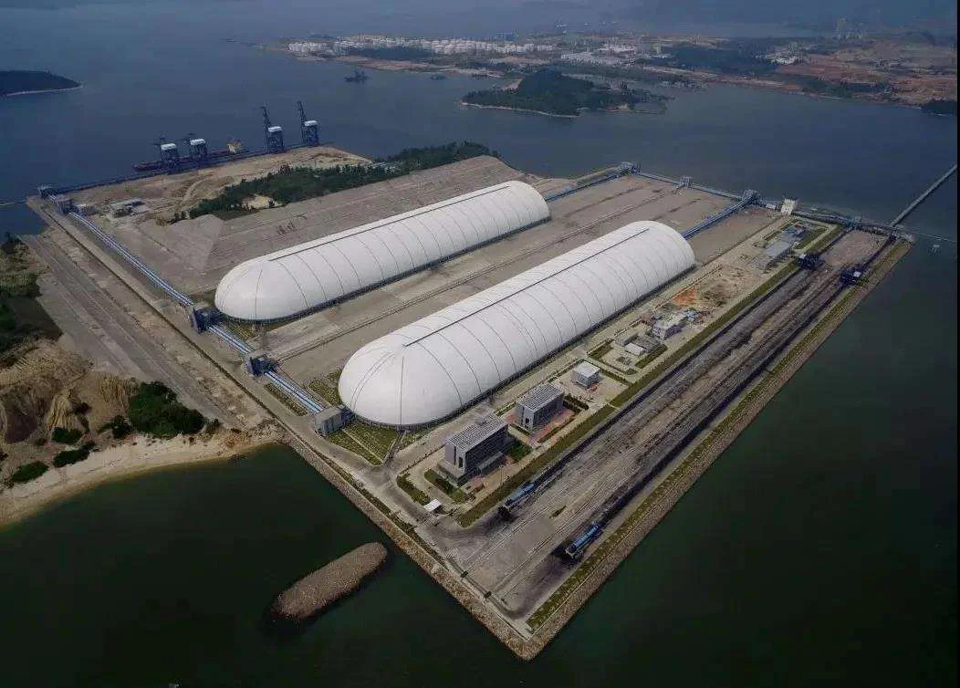
This case study explains the three-center shell geometry, the composite bolted-and-welded joint strategy, the bottom-chord support system, the engineering of a one-kilometre continuous structure through expansion joints, and the logistics of placing 7,000 tonnes of steel at a working port terminal.
Working at a live port terminal: the constraints that shaped the design
Port coal yards operate differently from power-plant stockyards, and the differences drove the design.
- Transshipment at scale: a port terminal receives, stacks and reclaims coal continuously across a much larger inventory than a single plant consumes. The yard footprint — and therefore the enclosure’s length — is set by berth-to-yard logistics and the stacking strategy, which is why this enclosure runs a full kilometre.
- Machinery envelope: stacker-reclaimers, yard conveyors, transfer towers and dozer haul roads all live inside the enclosure. The vault profile had to clear the tallest machinery at full extension while following the pile geometry where nothing tall exists — precisely the optimisation the three-center arc exists to make.
- Dust control at the waterfront: coal dust over a port is a compliance, safety and neighbourhood issue; wind-borne dust from an open yard can contaminate the terminal, the berths and the surrounding water. Full enclosure of the yard is the definitive solution, and the enclosure itself had to survive the coastal wind environment that made it necessary.
- Working within a live operation: the terminal could not pause while the shed went up. Erection sequencing had to partition the yard, keep reclaim access open, coordinate with the coal-moving schedule and operate within the port’s health-and-safety regime — all of which rewarded a structure built from repeatable, liftable grid blocks with a predictable programme.
Every one of these constraints pushed in one direction: a double-layer cylindrical shell grid — a two-way grid following a circular-arc cross-section — which delivers the clear interior, the repeatability and the erection friendliness a kilometre-long port enclosure demands.
The silkworm-cocoon profile: three centers instead of one
A single-circle vault is easy to describe but rarely optimal. Its true circular arc either stands too high where the machinery is low (wasting enclosed volume, roof area and material) or sits too low where the machinery is tall (forcing the whole profile up). The three-center arc — so named because its cross-section is drawn from three circular arcs with three centres — solves both problems at once.
How the three-center profile is built
Working inward from the base on each side, the profile begins with a tight side arc rising steeply from the spring line, transitions through a shallower intermediate arc, and meets the crown in a flat central arc. The three arcs are tangent-continuous — no kinks, no stress concentrations at the geometry, a smooth vault that follows the interior envelope of a silkworm cocoon set on end. The mathematics is simple to state and quietly sophisticated in effect: the local radius controls local behaviour, and each region of the cross-section can be tuned independently.
What the three centers buy
- Volume economy: the flat crown and tight sides track the pile-and-machine envelope, enclosing the coal and the equipment without enclosing a kilometre of empty cathedral. Less enclosed volume means less roof surface, less cladding, less maintenance and less steel.
- Wind response control: a flattened crown presents a gentler profile to coastal wind than a tall semicircle of the same span, reducing suction on the roof and pressure gradients around the eaves. In a typhoon-prone region, profile is a load case before it is aesthetics.
- Structural efficiency: a shell grid’s strength comes from curvature; the three-center form keeps useful curvature where it is needed (the sides carry the bending and thrust, the crown carries membrane action) instead of spending material on curvature that buys nothing.
- Interior machinery clearance: the steep side arcs clear the reclaim machine’s boom at the rail corridor while the profile returns quickly to hugging the pile — the single most operationally relevant property of the design.
The lesson the project teaches is transferable: in long-span enclosures, the cross-section is a design variable, not a default. Choosing the profile deliberately — three arcs instead of one — is a concrete example of engineering optimisation that the casual observer sees only as an elegant silhouette.
Composite joints and bottom-chord support across a kilometre
Two further decisions completed the structural system: composite sphere joints, and support at the bottom chord plane.
Bolted and welded composite sphere joints
Inside the shell grid, the large population of ordinary nodes uses bolted sphere connections — tapped steel spheres, member-end conical connectors, high-strength bolts tensioned on site with torque control. Bolting keeps the field operation fast, weather-tolerant and measurable across the tens of thousands of joints a kilometre-long shell contains. Where member forces exceed the efficient envelope of the bolted node — in the high-stress zones beside supports, at concentrated load points, and at the junctions between shell regions — welded sphere joints take over, transferring force through continuous material with no bolt-group ceiling.
Calling the result a composite joint system is deliberate: the two technologies coexist in one structure by design, each carrying the load regime it does best. The bolted population supplies speed, ductility and field-replaceability; the welded population supplies skeleton capacity where the envelope demands it. The economic and structural arguments are identical in kind to those documented in our GAC New Energy grid, but at port scale the numbers are more extreme: a kilometre of shell means the difference between thousands of fast, torque-verified connections and thousands of slow, weld-dependent ones — a difference measured in months on the critical path.
Bottom-chord support
The shell grid is delivered to its columns at the bottom chord plane. As in our Sinotruk assembly workshop, bottom-chord support removes the grid depth from the column height — refining structural economy across a kilometre of perimeter column lines — and keeps the usable interior clear height at the plane the machinery envelope demands. It also simplifies the support detail: the column cap connects concentrically to the bottom-chord node with no members passing through the support zone, and the reaction path into the foundation is direct.
Engineering a 1,000-metre structure: expansion, temperature and the kilometre problem
Long structures fail quietly in exactly one way before any other: temperature. A steel shell 1,000 metres long moves by several tens of centimetres between winter and summer — and by fractions of that each day — and if the structure does not accommodate the movement, it will eventually bend, buckle, or tear its own cladding apart. The kilometre problem is a thermal-movement problem, and it shaped the design at three levels.
Expansion joints
The 1,000 m enclosure is broken into segments by transverse expansion joints, each segment short enough that internal thermal stress stays inside acceptable envelopes. Every expansion joint is a full structural and architectural detail: the shell grid terminates cleanly, movement is absorbed by sliding/gapped connections in the cladding, drainage is interrupted and re-caught, and the joint stays weather-tight. The number and spacing of joints was itself an optimisation — too few and the segments are over-long (stress), too many and the shell’s longitudinal stiffness and wind bracing are needlessly interrupted.
Support mobility
Within each segment, one longitudinal position acts as the fixed reference (typically the centre or one end of the segment), and the other supports are detailed to slide, guided along the shell axis, so that the structure breathes from the fixed point outward. The sliding bearings and guided details were verified for the frictional reactions they impose on the shell under thermal displacement — a second-order effect that grows exactly linearly with building length.
The wind-bracing consequence
A kilometre of shell is a kilometre of sail in a typhoon wind. Longitudinal stability — resisting wind along the building — requires bracing systems placed in a pattern that does not fight the expansion joints: bracing bays act within each segment between joints, and the movement at each joint is absorbed while global stability is preserved. The geometry of the three-center shell, with its stiff side arcs, contributed the longitudinal capacity that kept the bracing demand reasonable.
None of this is visible in the final photograph. It is visible in the structure’s service life — and it is the difference between an enclosure that survives a decade of coastal seasons and one that develops its first rust-streaked cladding tear within a year or two.
7,000 tonnes of steel, choreographed to a live terminal
Approximately 7,000 tonnes of structural steelwork — chords, diagonals, spheres, connectors, columns, bracing, purlins and their connections — made the journey from Permanent Steel’s Xuzhou fabrication base to a working Guangdong port and into the air as a shell grid. The logistics were a project in themselves.
- Fabrication flow per segment: the shell was fabricated segment by segment so that delivery, erection and closure followed in a continuous cascade — each shop batch matched a defined site zone, and the coded parts for any zone arrived as a complete kit, never as a trickle.
- Transportation: member lengths and block sizes were checked against road and port access limits at every stage; the longest members moved on configured trailers with escorts, and the componentry was trucked as flat-stacked, coded loads built for rapid turnaround at an already-busy port gate.
- Erection within the live operation: the programme partitioned the yard so that erection fronts advanced behind operational zones; lifts, ground assembly plots and crane radii were coordinated with the terminal’s coal-moving schedule, and the block-lifting approach — grid modules pre-assembled at ground level and lifted as rigid units — minimised high-level work and its weather exposure.
- Quality gates unchanged: trial assembly of representative shell regions, 100% gauging of bolted spheres, NDT on the welded population, torque sampling on site — the same discipline applied at the 229 m Ningxia project applied here, because a 118 m shell at a working port has no more tolerance for connection failure than a world-record arch does.
The outcome is an enclosure that went up in controlled, verifiable increments and returned the yard to operation on schedule — the operational proof that extreme length and live-site logistics are compatible when fabrication and erection are engineered as one system.
Coastal wind, temperature and long-term durability
The service environment of this structure is unforgiving in a way inland sheds are not: typhoon-strength winds, high humidity, salt-laden coastal air and large diurnal temperature swings combine over a kilometre of roof surface. The design responded on every front.
- Wind actions: design wind loads followed the regional code provisions for the coastal exposure class, with the three-center profile’s aerodynamic benefit reflected in the pressure coefficients used for cladding and structure. Uplift-critical bolted connections were checked for tension capacity at the perimeter, where net suction is highest.
- Corrosion protection: the protective coating specification was selected for the marine-influenced atmosphere, with blast-cleaned surfaces, specified dry-film thickness and touch-up discipline at the field joints — because a kilometre of coastal steel is only as durable as its least-protected connection.
- Temperature and movement: expansion joint spacing, sliding supports and guided details were verified against the full seasonal and diurnal temperature range, as described above, so no lock-in stress accumulates in the shell.
- Seismic: the double-layer shell grid’s high redundancy gives it inherently ductile seismic behaviour; the design followed the national seismic provisions with the structure modelled as a three-dimensional coupled system.
- Serviceability: deflection criteria were set to protect the enclosure’s cladding and drainage at 118 m span with the machinery envelope undisturbed underneath.
Completion verification captured node coordinates against the model, confirmed camber after de-propping, and closed the documentation chain from mill certificate to final survey. The enclosure has since served the terminal through successive coastal seasons — the ordinary durability record that is the real performance claim of a structure designed for its environment rather than for its render.
Inside the shell: the environment the enclosure exists to create
An enclosure of this scale is more than a roof; it is the envelope within which the terminal’s air quality, fire safety and operating environment are managed. The design therefore integrated the systems that make the enclosed yard operational: monitored ventilation and dust-suppression provisions that manage the interior atmosphere during reclaiming and stacking; drainage that keeps yard runoff controlled and compliant; lighting and access provisions that keep inspection and maintenance safe across the full kilometre; and fire-safety measures appropriate to a coal storage occupancy, coordinated with the terminal’s procedures. None of these systems is glamorous, and all of them are the difference between an enclosed yard that performs and an enclosed yard that merely exists — the same discipline of thinking the operational reality of a structure before its rendering.
Shell grids, long-span systems and adjacent projects
This project is the longest expression of Permanent Steel’s cylindrical shell grid and long-span bulk-storage capability:
- Ningxia 229 m world-record beam-string arch truss — the extreme-span sibling in the same application family.
- Shanxi 220 m prestressed truss — a third structural system for the same storage function.
- Spatial grid structures — the grid and composite joint technology behind the shell.
- Metal roof and envelope — closing a kilometre of enclosure weather-tight.
- EPC engineering and erection services — the single-accountability model that makes a kilometre of steel choreography possible.
Planning a long or large coal enclosure at your terminal?
Send us your yard footprint, machinery envelope and operating constraints. Our port and bulk-storage engineering team will respond within 48 hours with a profile, joint and erection recommendation — and a structural quotation, not a square-metre guess.
Email the Engineering Team WhatsApp: +86 18621689980
Or call +86 516-83269982 and ask for the port and storage engineering team.