
GAC New Energy Production Capacity Expansion
An 85,000 m² EV assembly and process workshop spanned by a double-layer orthogonal square-pyramid flat grid — engineered, fabricated and erected by Jiangsu Permanent Steel Structure Co., Ltd. with a hybrid bolted-and-welded sphere joint system.
A factory sized for a production ramp-up — not for a roof
This project is a production capacity expansion for one of China’s leading new-energy vehicle (NEV) manufacturers. When an EV brand scales from tens of thousands to hundreds of thousands of units per year, the constraint is rarely the assembly line — it is the building that contains it. The entire 85,000 m² facility — body-shop floor, battery-pack integration bays, final assembly lines, and process-support mezzanines — sits under a single continuous roof structure: a double-layer orthogonal square-pyramid flat grid spanning the full width of the production bays without intermediate columns.
Permanent Steel’s scope covered the full engineering chain: structural analysis and connection design, fabrication of all grid members and nodes at our Xuzhou manufacturing base, surface treatment, trial assembly, transport to site, and erection of the complete structural system. Client and consultants received one accountable counterparty for the steelwork — not a chain of sub-vendors each deflecting responsibility onto the next. That single-accountability model is the reason the project held its structural programme while the surrounding civils and services packages moved in parallel.
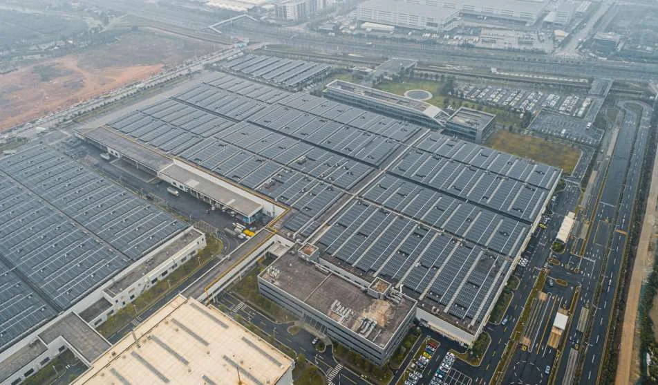
The structural brief was unusually demanding precisely because the building is ordinary. A 21st-century EV plant is a just-in-time machine: every square metre of floor must be usable, every column location is a conflict with a robot cell, an AGV route or an overhead utility spine. The client therefore specified maximum free span, maximum floor flexibility and maximum speed of enclosure. A double-layer grid fulfilled all three; this case study explains how, and why the joint strategy mattered as much as the geometry.
Why an EV factory cannot tolerate a column grid
Conventional steel portal-frame factory buildings rely on a column grid at 7.5–12 m centres. That geometry is perfectly adequate for warehouses and discrete assembly sheds. It is hostile to modern vehicle manufacturing for five reasons:
- Robot and tooling layouts follow product lines, not column lines. A body shop’s welding cells are positioned for a specific car platform; when the platform changes, the tooling moves and the columns do not. Every obstruction costs re-layout engineering and lost throughput.
- AGV and conveyor corridors need unbroken bands. Automated guided vehicles, skillets and power-and-free conveyors occupy continuous floor strips. A column line through those strips creates mandatory detours and traffic conflicts.
- Overhead services are dense. Busbars, compressed-air mains, coolant returns, ventilation ducts, fire-suppression headers and lighting runs all want to follow straight, predictable lanes. Columns force offsets and re-risers.
- Capacity upgrades must not require structural surgery. The roof structure of an EV plant is expected to outlive three or four vehicle generations. A portal frame’s column spacing is fixed at construction; a grid’s usable clear span is reserved from day one.
- Environmental control performance. Body-in-white painting and battery-assembly zones demand stable temperature, controlled humidity and clean-air filtration. Large uninterrupted roof planes are simpler to insulate, seal and service than roofs interrupted by structural elements and roof penetrations.
These are production-engineering arguments, and they decided the structural system before any steel was ordered. For a bay width in the 30–60 m class with full-height clarity beneath, the double-layer flat grid is the most economical steel solution available at Chinese fabrication norms — more material-efficient than trusses at this node count, faster to erect than on-site welded trusses, and inherently redundant because load can redistribute across two orthogonal directions of members.
The double-layer flat grid: the workhorse of large-span industrial roofs
A double-layer flat grid is a three-dimensional truss in which all members lie on one of two parallel planes — the top chord plane and the bottom chord plane — connected diagonally in between. The result behaves like a very deep plate: bending is carried primarily by the chord planes acting in tension and compression, while the diagonals transfer shear between them. Because the two chord planes are separated by the depth of the grid (typically 1/12 to 1/18 of the span in this class of building), the structure is many times stiffer than a single-layer plane frame of the same weight.
Why it won the comparison for this site
- Against the portal frame: the portal’s moment connections are fabrication-intensive, and its practical clear span is limited by member depth and crane clearance. At 30 m+ spans the grid’s three-dimensional action uses roughly 15–25% less steel for the same serviceability envelope.
- Against the plane truss: a lattice truss carries load in one direction only. The grid carries load in two directions, so critical members are smaller, local damage or overload is redistributed, and the two-way pattern permits balanced support layouts that a truss cannot exploit.
- Against the space frame with complex geometry: an orthogonal grid keeps node coordinates on a regular mathematical lattice. That regularity is the difference between a structure that can be numerically optimised in hours and one that consumes weeks of geometry classing — and it is decisive for fabrication repeatability.
The orthogonal square-pyramid (four-pyramid) configuration was specified because it is the most uniform, most repetitive two-way grid form: the standard module can be repeated in both plan directions with identical or near-identical members, which compresses engineering time, tooling setup in the workshop, and the inventory of unique parts.
The orthogonal square-pyramid configuration, explained
Envisage the grid as a chessboard. At every square of the board a pyramid is formed: its base is a bottom-chord square, its apex rises to the top chord plane where it is joined by top-chord members to the four neighbouring apexes. The diagonals running from apex to the four base corners complete each pyramid cell. Tiling this module across the plan produces the double-layer assembly that engineers call a two-way orthogonal square-pyramid grid (in Chinese practice, zhengfang sizhuijiao, the “positive four-angle pyramid”).
Three structural properties make this pattern ideal for an 85,000 m² manufacturing floor:
- Bi-directional load distribution. A load applied at any node flows toward the supports through both orthogonal families of grid lines. Edge and corner conditions are cleaner than in triangular or hexagonal geometries, and support reactions are well distributed to the perimeter columns.
- Uniform member hierarchy. In an optimised orthogonal grid, chord member sizes follow a smooth gradient from mid-span to support, and diagonal sizes vary over a narrow band. Fewer unique profiles means faster fabrication and simpler site identification — a real cost on a project with tens of thousands of members.
- Inherent redundancy. The two-way pattern provides alternate load paths. If a single member is dented by a fork-lift or a weld defect is found at inspection, the grid redistributes around the damage without progressive collapse — a resilience property that single-direction systems cannot offer at the same level.
The design was carried out to Chinese steel structure design standard GB 50017 with seismic and wind actions per GB 50011 and GB 50009, using full three-dimensional analysis rather than idealised frame models. Node eccentricities, member slenderness in compression, and second-order effects were accounted for directly; the supporting columns were modelled with the grid as a coupled system so that the real stiffness of the roof diaphragm influenced the portal behaviour of the columns, not the reverse.
Why hybrid bolted and welded sphere joints — and why it is the honest answer
Many grid roofs are marketed as “bolted” or “welded” as if the two were ideologies. In practice, the best-performing large industrial grids are hybrids, and this project is a clear case study of where each technology earns its place.
The bolted sphere joint
A bolted sphere node is a machine-turned steel sphere with drilled and tapped holes on its faces. Members terminating at the node end in a conical connector (a shear-key fitting) that is bolted to the sphere with high-strength bolts (grade 8.8 or 10.9). The connection is assembled in minutes with a torque wrench, requires no fire-permit hot work on site, and can be fully Quality-Controlled by measurable bolt torque rather than by welder skill. On this project, bolted nodes were used for the large majority of connections — the medium-load interior members that dominate the member count of a grid.
The economics of bolting are compelling at volume: welding a sphere node on site requires positioning the member, tacking, multiple passes of qualified welder effort, NDT inspection and rework risk. A bolted node on the same member is installed in under a fifth of the labour time and with zero welding consumables. On an 85,000 m² grid with tens of thousands of joints, that difference is measured in months of erection programme — and a windproof, rainproof bolting operation is far less weather-sensitive than site welding.
The welded sphere joint
The welded sphere is the classic Chinese spatial-structure node first developed in the 1960s precisely for grids of this kind: tubular members are profile-cut and butt-welded onto a hollow sphere shell. Its advantage is connection capacity — a welded node can accept substantially higher member forces in all directions than a practical bolted node, because the bolted node’s capacity is limited by the bolt group geometry, sphere thread engagement and the fit-forging precision of the connectors.
On this project, welded nodes were specified wherever member forces sat above the efficient domain of the bolted node:
- in the high-stress zones adjacent to support columns, where chord forces peak;
- around concentrated load points — rooftop plant platforms, heavy equipment suspension points and crane-runway integration lines;
- at column-to-grid connection details where a welded node gives cleaner force transfer to the column cap;
- in edge and corner zones where asymmetric member forces would overload the most convenient bolt pattern.
Cost optimisation without losing redundancy
The hybrid strategy is a direct cost-vs-robustness optimisation, and it works because the two joint types fail differently. A bolted connection shows measurable slip before ultimate load and behaves semi-rigidly; a welded connection is rigid until fracture. Placing welded joints on the hottest load paths and bolted joints on the distribution grid means the structure’s overall rigidity is governed where it matters (the high-force skeleton), while the huge population of ordinary joints remains fast, economic and field-replaceable. If a bolted node is ever damaged, it can be unbolted and swapped without cutting. That maintainability is genuinely valuable in a production building that cannot pause for roof surgery.
The design rule we applied was simple and defensible: bolt where the fasteners can carry the envelope of forces with reserve; weld where they cannot. Where both were acceptable, the bolted solution won on programme and total cost. The result is a hybrid system whose redundancy is strictly greater than either uniform system, because a failure in the bolted population is ductile and local, while the welded skeleton keeps the overall grid coherent.
From Xuzhou workshop to clear-span structure: how it was built
Every member, sphere and connector for this grid was produced at Permanent Steel’s own fabrication base in Xuzhou — a 300-mu site equipped for the scale this project demanded. Line flow was organised so that chord members, diagonals, spheres, connectors and end plates moved through CNC cutting, hole drilling, shot blasting and priming without back-tracking.
Fabrication control
- Steel: structural hollow sections and plate in Q355B grade were procured with mill certificates (EN 10204 3.1 equivalents) and code-stamped per part, so every member can be traced to its heat and mechanical test results.
- Spheres: bolted spheres were forged and machined to tolerance; face planarity and thread position were gauged 100%. Welded spheres were fabricated from pressed hemispheres with full-penetration girth welds subjected to 100% ultrasonic testing.
- Member end prep: diagonal end fittings and welded member ends were cut by CNC with numerically controlled bevels, eliminating the manual flame-cutting variance that undermines field fit-up.
- Shot blasting and primer: all surfaces were blast-cleaned to Sa 2.5 and primed before dispatch, with the coating specification verified by DFT gauge on a statistical sample per batch.
Trial assembly
Before mass fabrication, representative bays — including corner modules, support modules and typical interior modules — were trial-assembled in the workshop on a surveyed strong floor. Node coordinates were checked against the model, and bolt fit was verified with the actual connectors. The trial assembly served as the quality gate that de-risked every later module: the geometry classing and bolt-fit problems were found in Xuzhou, where they cost days, rather than on site, where they would have cost weeks.
Erection sequence
Where site access, foundation construction and the crane floor allowed, the grid was erected in shop-built blocks: clusters of modules assembled on the ground with permanently tensioned bolts, then lifted as rigid units onto the support columns and connected at high level. Blocks were dimensionally reconciled against survey control before lifting; temporary stabilisation guys were released only after the adjacent block connections were made. The two-way regularity of the orthogonal pyramid configuration made block boundaries predictable, so every lifting geometry and temporary support reaction was computed in advance rather than improvised.
High-strength bolt tightening was executed in a defined order from the centre of each block outward, with torque control verified by calibrated wrenches and a field sampling rate above the code minimum. Site welds on the welded-node zones were performed by certified welders, inspected by MPI or UT per the specification, and reconciled against the fabricated-member weld records in a single NDT register — one file that covered every weld, on- and off-site, in the structure.
Code compliance, serviceability and the loads that really mattered
A factory roof is judged by deflection and durability more than by strength — a grid that is strong but sags measurably will crack its cladding sheeting, bind its roller doors and alarm the process engineers. The serviceability criteria for this structure were therefore set tighter than the minimum code provisions:
- Deflection: the grid was proportioned so that dead-plus-live deflection stays within the code limit for this span class, with additional pre-camber built into the bottom chord plane so that the finished soffit appears level under dead load — the aesthetic expectation of a process hall where suspended services follow a level datum.
- Wind: uplift and suction on a large flat roof plane were evaluated per GB 50009 with regional wind parameters; uplift-critical bolted connections were checked for the connection’s ability to carry tension as well as shear, and anchor/column-cap detailing was proportioned for net uplift at the perimeter.
- Seismic: the two-way grid’s redundancy translated directly into favourable seismic behaviour — many equal members and ductile connections allow energy dissipation across the whole structure rather than concentration in a few plastic hinges.
- Thermal movement: expansion provisions were placed at the perimeter supports with sliding bearings and guided details, so that a 200 m+ roof expanse breathes thermally without locking internal stresses into the grid or the cladding.
- Fire: the roof members receive fire-resistance treatment in the critical zones per the building code’s classification of the occupancy, with the coating specification selected for adhesion on blast-cleaned primed steel.
The structural completion was verified by independent surveys against the design model: node coordinates within tolerance, camber confirmed after de-propping, and the finished grid exhibiting no measurable settlement differential across the support lines three months after completion — the end-of-story of every large-span roof delivered by a team that keeps its own erection records as evidence, not as an afterthought.
The systems behind this structure
This project is one application of Permanent Steel’s spatial grid technology line. If your facility plan raises the same questions — how far can the roof span, what joint system suits my loads, how fast can the steel land on site — the following pages document the underlying technology and adjacent capabilities:
- Bolted sphere grid structures — the joint system that dominated this project, with capacity, tolerance and field-assembly rationale.
- Industrial building systems — envelope, crane and process integration for large manufacturing facilities.
- Metal roof and envelope — the cladding and roofing layers that convert the grid into a serviceable building.
- Sinotruk heavy truck assembly workshop — a comparable 77,000 m² double-layer grid serving a different industrial process.
- Engineering, fabrication and erection services — the full single-accountability delivery chain.
Scope your own column-free production hall
Send us your floor plan, bay width, crane requirements or process layout. Our engineers will respond within 24 hours with span, framing and joint recommendations — and a structural quotation, not a square-metre price.
Email the Engineering Team WhatsApp: +86 18621689980
Or call +86 516-83269982 and ask for the industrial systems team.