
Sinotruk Intelligent Connected Heavy Truck Assembly Workshop
A 77,000 m² truck assembly hall spanned by a double-layer planar grid with hybrid bolted and welded sphere joints — supported on the bottom chord to keep columns short, cranes unimpeded and 200-metre production lines continuous.
| Project Type | Heavy-truck intelligent assembly workshop |
|---|---|
| Location | China |
| Structural System | Double-layer planar grid roof with bottom-chord support; hybrid bolted/welded node strategy |
| Key Dimensions | 77,000 m² building area; continuous production bays with overhead crane integration |
| Steel Quantity | Available on request from project records |
| Supply Scope | Grid roof design support, fabrication, crane-runway reaction coordination and erection support |
| Design Basis | Crane dynamic loads, service suspension points, member tolerance control and clear production-line geometry |
| Installation / Logistics | Bottom-chord support reduces column length; crane and lifting plan available on request for a comparable workshop |
| Client / Completion Year | Available on request; public project identity shown without unsupported client claims |
Need exact tonnage, installation schedule, crane plan or container count for a comparable project? Request a technical quote and send your drawings or sketch.
An assembly line measured in hundreds of metres, roofed without interruption
Sinotruk — China National Heavy Duty Truck Group — is the country’s oldest and one of its largest heavy-truck manufacturers, producing trucks whose frames, cabs and drivelines are assembled in long linear process lines. This project delivers a 77,000 m² intelligent connected heavy truck assembly workshop: the shell within which chassis frames travel through frame stations, cab marriage, driveline installation and final engineering checks without once being forced to deviate around a column.
The roof system engineered, fabricated and erected by Permanent Steel is a double-layer planar grid — two parallel chord planes connected by diagonals — configured on an orthogonal module and supported at the bottom chord level. The selection of bottom-chord support was not an aesthetic choice or an afterthought; it was dictated by the process inside. This case study examines the physics and the economics of that decision, the integration of heavy crane loads into a three-dimensional grid, and the joint strategy (bolted spheres for the distribution network, welded spheres for the load skeleton) that kept programme and integrity in balance.
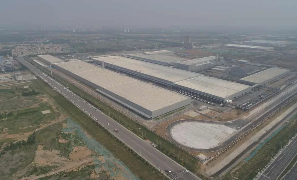
Truck assembly is distinguished from passenger-vehicle assembly by scale and weight. A heavy-duty chassis line handles frames up to 12 metres and gross weight classes in the tens of tonnes; the tooling is massive; overhead cranes lift complete cab and powertrain assemblies; and the same line must accommodate multiple truck platforms with minimal reconfiguration. None of that is possible behind a forest of interior columns. The building had to be, in effect, one enormous unobstructed volume — and the steel had to deliver it economically enough to justify a grid structure over a conventional frame on a construction budget measured with engineering discipline.
What 77,000 m² of truck assembly actually demands of steel
The functional brief for this workshop can be compressed into three structural requirements, each of which shaped the design at a fundamental level:
- Continuous long-bay clear span. Chassis and assembly lines run in straight, parallel bays that extend several hundred metres. Any column inside the envelope forces the line to dog-leg — an unacceptable compromise for a process that feeds through conveyors and skids. The grid’s usable clear span across the full bay width eliminated the problem rather than reducing it.
- Overhead crane and hoist capacity. Component delivery, cab handling and heavy sub-assembly moves are served by overhead cranes on runway beams at high level. The roof structure had to accommodate the runway loads, the crane reactions, the travelling loads and the dynamic impact coefficients — not as an afterthought bolted to a finished roof, but as a primary load case integrated into the grid model from the start.
- Service suspension and future flexibility. Lighting, ventilation, process exhaust, compressed air, power distribution and the assembly line’s own catenary support frames are suspended from the structure. The underside of the grid is a ready-made spatial grid of suspension points — any node can carry a concentrated service load with local verification, which is exactly how flexibility is achieved in a building that will be re-tooled repeatedly over its life.
These three requirements pushed the design toward the double-layer planar grid for the same reasons as any large-process hall, but the heavy crane case and the unusually long continuous bays gave the project its own engineering character — and put the bottom-chord support decision at the centre of the narrative.
Bottom-chord support: why this workshop stands on the lower chord plane
A double-layer grid can be delivered to its supports in two fundamentally different ways. In top-chord support, the columns rise through the depth of the grid to connect at the upper chord plane; in bottom-chord support, the column caps terminate at the lower chord plane and the grid bears directly on them. The difference sounds like a detail. It changes the entire structure.
Column economy
Supporting at the bottom chord removes the grid depth from the column length. With a grid depth of roughly 3–4 m at this span class, every column is 3–4 m shorter — and in a 77,000 m² hall with perimeter and internal column lines at close spacing, that is thousands of tonnes-metres of column material removed, reduced buckling length, smaller foundations and reduced wind moment. The saving is real and it is distributed across every support in the building.
Clear height and service integration
The clear height that matters to a production engineer is measured from the finished floor to the lowest obstruction — which in a grid building is the bottom chord plane. Bottom-chord support keeps that usable datum at its designed level without forcing longer columns; the grid depth effectively sits above the support plane rather than consuming the usable volume. Suspended services, crane runway brackets and mezzanine structures all attach to the column lines below the chord plane, where the geometry is simple and the steel is straight.
Member and node coordination
In top-chord support, columns pass through the grid band and must be detailed to avoid conflicting with diagonal members on the way up — a coordination problem at every column, with structural and aesthetic consequences. Bottom-chord support eliminates the conflict entirely: the column cap bolts onto the bottom-chord node, the diagonals above it are uninterrupted, and the load path into the column is direct and concentric. The connection detail at the cap is simple, inspectable and standardised — exactly the attributes that keep an erection programme honest.
When is top-chord support still right?
Intellectual honesty requires the caveat: top-chord support is not always wrong. It is typically chosen where the grid must be held high above its base for structural reasons — for example when the roof plane is deep enough to justify a Vierendeel-like interaction, or when architectural expression wants the grid hovering above glazed walls. For a heavy industrial assembly hall, none of those motives apply, and the engineering case for bottom-chord support is unambiguous. The building is 3–4 m of columns lighter for it, and the process space is exactly as deep as the process needs.
Bringing heavy crane reactions into a three-dimensional grid
An overhead crane is one of the most punishing loads an industrial building ever receives. Its reactions are concentrated, its dynamic amplification is significant, and its travel means the reaction point moves along the runway beam hour after hour. The classic solution — a rigid portal frame with the crane runway on integral columns — was not available here precisely because interior columns were banned from the process space. The grid itself had to absorb the cranes.
How the grid carries crane loads
Crane runway girders run longitudinally along the column lines just below the bottom chord plane, supported on craneway brackets welded to the column stubs. From the bracket, the reaction flows into the column and straight up into the bottom-chord node at the column cap. From that node the double-layer grid disseminates the force in two directions: chord forces spread the reaction along the bottom chord plane, while the diagonals lift it into the top chord plane where the roof diaphragm distributes it across the whole grid footprint. The marine-sized advantage of a two-way grid over a planar truss is that a 50 t crane reaction is shared by dozens of members through local redistribution rather than being flung down a single load path.
What the analysis had to capture
- Dynamic impact factors applied to the crane loads per the governing code — the vertical impact of loaded travel, the lateral surge from trolley acceleration and the longitudinal traction forces, each with its own coefficient.
- Runway travel position: the critical reaction envelope occurs at defined positions along the runway; the grid was modelled with the travelling crane at its worst-case stations, not as a static equivalent.
- Local node design: bottom-chord nodes carrying crane reactions were designed as welded high-capacity nodes even where the surrounding population is bolted — the hybrid joint policy applied at the load skeleton, not just in the roof.
- Fatigue and repeated load: crane cycles subject the supporting details to repeated stress ranges; weld details at craneway connections were designed and detailed with fatigue in mind, beyond the static code check.
The outcome is a crane-carrying grid whose runway system is fully integrated: the crane service loads are as much a part of the structural identity as the roof snow load, and the grid’s redundancy converts what would be a reliability risk in a portal frame into a distributed, predictable load path.
Bolted spheres for the network, welded spheres for the skeleton
The hybrid joint philosophy applied on this project is the same one Permanent Steel applies across its large industrial grids, and it deserves an explicit defence because it is frequently misunderstood as a compromise between two competing technologies. It is not a compromise; it is an optimisation with two variables — connection capacity and connection cost — and the two technologies occupy different parts of both scales.
The bolted population
Bolted sphere joints dominate the interior of the grid: machine-turned spheres with tapped faces, connected to member-end conical fittings by high-strength bolts torque-controlled on site. They are the fastest, most weather-tolerant and most measurable connection in industrial steelwork — a bolted connection is verified by controlled torque, not by welder craft. In a grid with tens of thousands of joints, the programme effect of bolting the ordinary population is the difference between a twelve-month roof and a twenty-month roof.
The welded population
Welded sphere joints take over where member forces exceed the efficient envelope of any practical bolted node — the high-compression chord zones near supports, the crane-reaction nodes, corner and edge regions with unbalanced forces, and every junction between the grid and its support columns. A welded node transfers force through continuous material with no bolt-group limit; its capacities track the member capacities instead of capping them. Every welded node on this project was produced in our workshop or by certified site welders, with 100% NDT coverage as specified, because a welded joint’s integrity belongs to the weld — and the weld is never left to chance.
The optimisation rule
The practical engineering rule we applied: classify every node by its worst-case force envelope; bolt where fasteners carry it with reserve, weld where they cannot. The result is a structure whose welded skeleton guarantees global rigidity exactly where rigidity is needed, and whose bolted majority buys speed, substitutability and ductility everywhere else. This is the engineering answer to the false question of “bolted or welded?” — and the cost model of this 77,000 m² project is the evidence that it is the right answer at industrial scale.
Building the hall: fabrication control and the erection sequence
All grid steel for this workshop was fabricated at Permanent Steel’s Xuzhou base. Members arrived on site as a fully coded kit — every chord, diagonal, sphere, connector and end plate traceable to its mill certificate and cutting batch — which is the prerequisite for a site operation that could not afford to stop and argue about a single out-of-tolerance part.
Pre-erection controls
- Trial assembly of representative modules — support nodes, crane-integration bays and typical interior bays — on a surveyed strong floor in the workshop, closing the loop on geometry before mass production.
- 100% gauging of spheres: face planarity, thread position and sphere diameter checked against the modelling tolerances, because a sphere is the one component whose error propagates into every member it connects.
- CNC end prep with numerically controlled bevels for all welded member ends, eliminating flame-cut variance at the joint where fit matters most.
- Coating: blast-cleaning to Sa 2.5 and primer before dispatch, with dry-film-thickness verification on a statistical sample per batch.
Erection logic
The erection concept exploited the grid’s regularity: modules were pre-assembled at ground level into blocks sized for the crane configuration, then lifted and docked onto the column caps in a defined sequence from one end of the hall toward the other. Temporary bracing was computed and pre-installed so the emerging structure was self-stable at every intermediate stage — a steel skeleton never stands on goodwill. After each block was connected, high-strength bolts were tensioned in the prescribed sequence from block centre outward, and site-welded nodes were completed as the welding crews followed the erection front, with NDT results logged in the same register that held the workshop records.
Level control was the quiet hero of the programme: column caps were surveyed before each dock, block coordinates reconciled against the model after each lift, and the finished bottom chord plane verified within tolerance across the full 77,000 m². Deviation that is caught during erection costs hours; deviation that survives to the cladding stage costs the building’s service life.
Serviceability, seismic behaviour and the loads that govern
The governing cases of a heavy-truck plant are not exotic, but they are unforgiving: deflection must not disturb conveyor alignment or crane runway level; seismic response must exploit — not fight — the grid’s redundancy; and thermal movement over continuous bays of several hundred metres must be absorbed without locking stresses into the structure.
- Deflection and camber: the grid was analysed for the full envelope of dead, live and crane-induced loads; pre-camber was built into the fabrication geometry so the soffit reads level under dead load and service deflections remain inside the code envelopes that protect cladding and suspended services.
- Seismic: the two-way grid’s high redundancy and ductile bolted population give it a favourable seismic energy-dissipation profile. The design followed GB 50011 with the structure modelled as a three-dimensional coupled system — grid, columns and craneway — so that no member was checked in isolation from the system it works within.
- Wind and thermal: large roof planes attract pronounced uplift and suction; uplift-critical connections were verified for tension, and expansion provisions at the support system allow the structure to breathe over temperature cycles without accumulating stresses in the chord planes.
- Crane-related durability: details subjected to repeated crane cycles were proportioned beyond the static checks, with weld geometry and connection stiffness selected to control stress ranges at the fatigue-sensitive locations.
Completion verification followed the same discipline: independent surveying of node coordinates against the design model, camber confirmed after de-propping, and a documentation package that ties every member, weld, bolt lot and coating batch to its inspection record. That package is not bureaucracy; it is the evidence on which a production-critical building is trusted for the next four decades.
The systems behind this workshop
This workshop sits inside Permanent Steel’s spatial grid and industrial building technology lines. The pages below document the underlying systems and the adjacent projects that share this engineering DNA:
- Bolted sphere grid structures — node technology, capacities and field-assembly rationale.
- Industrial building systems — envelope, crane and process integration for heavy manufacturing.
- Metal roof and envelope — converting the grid into a serviceable, insulated building shell.
- GAC New Energy expansion — a comparable double-layer grid for a different manufacturing process.
- Ningxia 229 m coal shed — where the same grid engineering family is pushed to world-record span.
Engineer your heavy manufacturing hall
Send us your process layout, crane schedule and bay requirements. Our engineers will respond within 24 hours with span, support and joint recommendations — and a structural quotation, not a square-metre price.
Email the Engineering Team WhatsApp Our Engineer WhatsApp: +86 18621689980
Or call +86 516-83269982 and ask for the industrial systems team.