
The 748-Meter Steel Covered Bridge
A 748-meter covered bridge — China's first Qin-style two-level steel pedestrian landscape bridge — combining pedestrian circulation, commercial space and cultural architecture in a single enclosed steel structure. Where the traditional Chinese langqiao (covered bridge) tradition meets modern prefabricated steel bridge engineering, delivered by Permanent Steel with a steel truss structure, a steel deck and a steel roof envelope.
A Bridge That Is Also a Building
The covered bridge is both transit infrastructure and public space: a 748-meter continuous enclosure that carries pedestrian circulation through a sheltered promenade while housing commercial bays along its length.
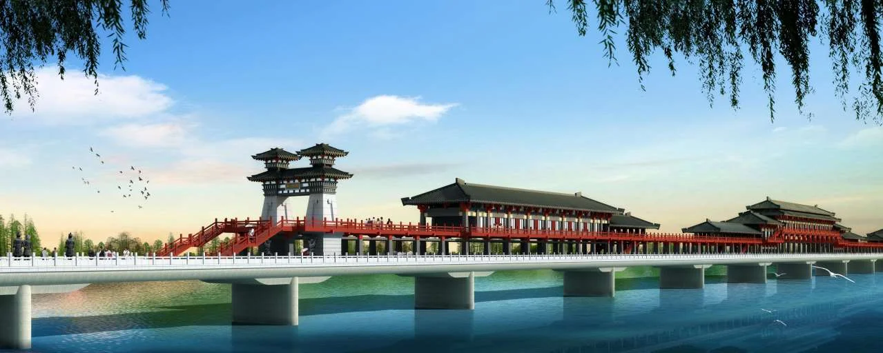
The project spans 748 meters in total length with a 14-meter-wide deck, making it China's first Qin-style two-level steel pedestrian landscape bridge. It is a closed, weather-protected crossing: the deck is enclosed by a roofed and walled envelope, so the space inside the bridge is usable in rain, wind, snow and summer sun. This is not a decorative canopy over a highway bridge — it is a building that happens to span a river, and its two functions are co-equal in the design: pedestrian circulation (a continuous public route from one bank to the other) and commercial function (retail bays, stalls and gathering spaces distributed along the promenade). The economics of the covered form depend on exactly this dual use: the cost of the roof and enclosure is justified by the value of the sheltered space it creates, echoing the way traditional covered bridges hosted shops, pavilions and social life.
For Permanent Steel, the project is a landmark delivery of our steel structure bridge system. The structure is a steel truss + steel deck + steel roof envelope system: triangulated steel trusses carry the long-span loads; a steel deck plate distributes pedestrian and commercial loads into the trusses; and a steel-framed roof and wall envelope closes the bridge against the elements. Every major component — truss segments, deck units, roof frames and cladding — was fabricated in our 300+ mu Xuzhou facility and erected on site with bolted connections, which explains both the schedule and the dimensional precision of the finished structure.
The Langqiao Tradition: A Roof Over the River
Covered bridges — langqiao (廊桥) in Chinese — are among the oldest and most culturally loaded structures in Chinese architectural history. The form is documented from the Tang dynasty (618–907) onward and reached its classic expression in the Song dynasty (960–1279), when the celebrated “rainbow bridge” (虹桥) captured in Zhang Zeduan's 12th-century scroll Along the River During the Qingming Festival showed a woven-timber arch span crowded with merchants and pedestrians. In the mountainous Min-Zhe region of southeast China, communities built sophisticated timber-arch covered bridges whose interlocking beam lattices needed no nails, and village elites competed to build the longest and most beautiful — the bridge was the village's signature structure, often the single most expensive public work a community ever undertook.
Why did communities roof their bridges? Three reasons, all of which remain valid today. Climate: a roof and walls turn a river crossing into a year-round, all-weather route and gathering place. Commerce: covered bridges traditionally hosted stalls, shops and teahouses along their length, turning transit into economic activity — the tolls and rents often paid for the bridge's own maintenance. Community: the covered bridge was the village's living room: a place to rest, shelter from a storm, meet neighbors, conduct business and hold festivals. Feng-shui tradition held that a covered bridge at the village entrance “locked in” prosperity and blocked harmful influences from flowing downstream.
The 748-meter project is a direct descendant of this tradition, executed in steel. The historical form was limited by its material: timber spans of 20–40 meters required massive arch lattices, and the wood structure needed constant replacement of rot-prone members. By translating the covered bridge into a prefabricated steel truss system, the cultural form is extended to dimensions, fire performance, service life and maintenance economics that timber could never reach — while preserving the essential character of the building type: a sheltered, sociable, commercially alive space spanning water.
Steel Truss + Steel Deck + Steel Roof Envelope
The bridge is engineered as three co-working steel systems, each factory-fabricated and field-bolted.
1. Main Structure: Steel Trusses
The primary load path is a series of plane steel trusses — typically Warren or Pratt configurations — spanning between intermediate piers along the 748-meter length. Triangular web geometry converts the vertical loads of people, shops, roof and self-weight into axial tension and compression in the chord and web members, so a truss is far lighter than a solid beam of the same span. Chord and web members are fabricated from rolled sections and welded plate, with shop-welded connections at the panel points and high-strength bolted field connections at segment boundaries. Longitudinal stability comes from a continuous top-chord bracing system and portal frames at the pier lines, which together distribute wind and braking forces to the foundations.
2. Steel Deck
Walking surfaces and commercial floors are formed by a steel deck system: prefabricated steel plate or orthotropic deck units continuously welded or bolted to the truss top chords and cross-girders. The steel deck is stiffer and thinner than a concrete slab of equivalent span, subtracting dead weight from the already-massive 748-meter structure, and it acts as a top flange to the cross-girders, creating a partially composite section that adds stiffness without added depth. A thin skid-resistant wearing course is applied over the plate — wearing course, not structural slab — because the structure beneath it is already complete: a decisive schedule advantage that a concrete deck cannot offer.
3. Steel Roof & Wall Envelope
The enclosure that makes the bridge “covered” is itself a steel structure: roof trusses or portal frames rise from the deck edge lines every bay, carrying profiled steel or sandwich-panel roofing, while the walls are steel-framed with insulated cladding and glazed openings where views are wanted. The envelope does three structural jobs beyond shelter: it resists wind as a large bluff body (transferred through roof bracing and diaphragm action back to the trusses); it carries snow and maintenance loads; and it provides lateral restraint to the top chords of the main trusses, so the roof structure and the bridge structure work as one continuous system rather than as two stacked systems.
Every structural member is shop-fabricated, trial-assembled where required, and delivered to site ready for bolted erection — the discipline that allows a 748-meter enclosed bridge to be completed on a fixed schedule.
Why Steel Instead of Traditional Wood
The covered bridge was born in timber. The 748-meter project is built in steel — deliberately, for five engineering reasons that a traditional timber structure cannot answer at this scale.
Longer Spans
Timber-arch covered bridges reach economical spans of roughly 20–40 meters before member sizes, joint complexity and weight become prohibitive. A steel truss of the same visual slenderness spans 40–80 meters with axial efficiency, and the panelized truss system repeats economically over the full 748-meter length. Fewer, longer spans mean fewer piers in the river — less flood obstruction, less foundation work, smaller environmental footprint in the waterway.
Fire Resistance
Timber is a fuel: an enclosed timber bridge concentrates its own fire load, and covered-bridge fires are historically catastrophic and fast. Structural steel is non-combustible — it does not contribute fuel — and its load capacity is maintained into the fire until temperatures exceed roughly 500–550°C, where protected members (intumescent coating or enclosure boarding) buy the rated resistance the code requires for a bridge occupied by shops and pedestrians. Fire safety in a commercial covered bridge is a code obligation and a public-safety question; timber cannot compete on either.
Durability Against Rot, Insects and Climate
The interior of a covered bridge is a hostile environment for wood: humidity from the river below, drying cycles from sun, condensation on the underside of the roof, and insect attack in warm climates. Timber members decay at their joints first, where water penetrates and cannot dry — exactly where the traditional structure is most loaded. Galvanized and coated steel has no biological decay path: no rot, no termites, no fungal growth. Its corrosion risk is managed at the coating specification stage (zinc-rich primer + epoxy + polyurethane systems for the bridge's corrosivity category), and it is inspectable and re-coatable in service.
Maintenance Cost Over the Service Life
A large timber bridge needs a permanent maintenance program: member replacement, joint repair and structural reassessment on a cycle measured in years. A steel truss system's primary maintenance is coating renewal at intervals of 15–25 years, with bolted field connections that can be inspected, tension-checked and replaced component-by-component without closing the bridge. Using 100-year life-cycle cost comparisons, the steel system's lower recurring maintenance outweighs its higher first cost — and keeps the bridge open to the public and its tenants throughout its life.
Prefabrication and Schedule Certainty
Timber covered bridges are built laboriously on site, joint by joint. The steel system is fabricated in our factory while the foundations are built in the river — two work fronts on one schedule — then assembled with bolted connections in predictable daily increments. Factory fabrication also removes the weather risk that governs timber erection: welding, coating and tolerancing happen under the roof of a 100,000 m² workshop, not on the river.
Three Load Cases That Define a 748-Meter Enclosed Bridge
1. Wind Load on a Fully Enclosed Bridge
An open bridge deck presents a small lateral face to the wind; the members are slender and largely transparent to airflow. A covered bridge is a solid wall 748 meters long — effectively a building lying across the river — and its solidity ratio approaches 1.0, meaning nearly all incident wind is converted into lateral force on the structure. The engineering response operates at three levels: the envelope's own bracing (roof and wall diagonals that carry wind from the cladding to the trusses); the top-chord lateral system that distributes wind to the portal frames at each pier; and the foundation, where the additional lateral load is delivered to the piers and their piles. The roof additionally experiences uplift — wind over an enclosed roof generates suction that must be resisted by roof anchorage into the top chords — and the long slender roof, like the bridge itself, is checked for vortex shedding: if the frequency of alternating eddies shed from the roof matches the structure's natural frequency, sustained oscillation can develop, so member stiffness and mass distribution are tuned to keep shedding frequencies out of the resonant range for the design wind speeds.
2. Thermal Expansion Across 748 Meters
Steel expands and contracts with temperature at roughly 12 × 10<sup>-6</sup> per °C. Multiply that by a seasonal temperature swing of 30–50°C and a continuous structure 748 meters long, and the bridge would try to grow or shrink by 270–450 mm between midwinter and midsummer. Restrain that movement and the structure generates enormous locked-in forces — so it is not restrained; it is accommodated. The bridge is divided into movement-controlled segments by expansion joints and slotted/elastomeric bearings at the pier lines, typically every 60–90 meters, so that no segment accumulates more thermal movement than its bearings and joint detailing can absorb. The envelope is treated the same way: roof and wall cladding joints, glazing and service runs are detailed with compatible movement allowances, so the 748-meter building breathes as designed without cracking finishes or overloading connections. Thermal analysis of the combined structure-and-envelope system is one of the defining calculations of this project — a load case that simply does not exist on a 50-meter bridge.
3. Pedestrian-Induced Vibration and Resonance
People walk at a rhythm: about 1.6–2.4 Hz vertical stepping frequency, and a sideways sway near 1 Hz. A bridge that is too flexible can enter resonance — the crowd's rhythmic loading synchronizes with the structure's natural frequency and amplifies until the deck sways perceptibly — the mechanism that famously closed London's Millennium Bridge on its opening day and forced the retrofits that followed. In a 748-meter covered bridge carrying continuous pedestrian and commercial traffic, comfort is a structural requirement, not an afterthought: the trusses and steel deck are proportioned so the fundamental vertical frequency of each span stays above roughly 3 Hz (ISO 10137 / EN 1990-A2 comfort criteria), keeping excitation frequencies clear of the structure's dynamic response. Where one or two spans cannot reach the target by stiffness alone, tuned mass dampers are added at the worst-response locations to absorb vibration energy at the offending frequency. The commercial bays add a second dynamic consideration — crowd loading at events and markets, which is treated as a distinct loading case with its own comfort and acceleration limits.
Shop-Fabricated Segments, Bolted Together On Site
The schedule logic of the project rests on one decision: do the steelwork in the factory, not in the river.
Each 748-meter bridge is broken into shop-fabricated truss segments sized by transport constraints — typically 12–18 meters long for road delivery by low-loader — with chord and web members welded at the panel points under controlled shop conditions, using certified welders and full NDT inspection where the design requires. Connection points between segments are left with bolt-ready gussets and high-strength friction-grip bolts (typically 10.9 grade), so the field joint is mechanical, quick and inspectable — no field welding of major load paths.
Before delivery, critical segments undergo trial assembly at the works: adjacent segments are bolted together on the shop floor, the full-joint geometry is checked against the erection drawings, and camber — the deliberate pre-bend that lets the truss deflect to level under live load — is verified. Trial assembly converts field risk into factory risk, where it can be measured and corrected before anything reaches the river. Members receive their full coating system in the shop, with touch-up only at the field joints.
On site, erection followed a repeating cycle: crane lifts a truss segment onto its pier bearings, a second segment is aligned and bolted, the top-chord bracing is completed to stabilize the pair, and the cycle advances to the next bay. The steel deck units follow the trusses closely, so the bridge grows as a complete working structure — truss, deck, and subsequently envelope — rather than as an exposed skeleton awaiting later systems.
What Factory Fabrication Buys This Project
- Quality: welding, coating and geometry performed under controlled factory conditions
- Parallel schedule: foundations and steelwork advance simultaneously
- Weather independence: no rain-day or wind-day penalties on critical joints
- Repeatability: a proven segment cycle repeats across 30+ spans with shrinking learning curve
- Traceability: every segment carries a shop record linking its steel certificates, welds and NDT to its position in the bridge
The manufacturing systems behind this project — CNC plate cutting, automated welding, coating and transport logistics — are detailed in our core manufacturing technologies page.
The Bridge as a Building: Structure and Space as One Design
The defining architectural decision of this project is that the enclosure is structure, not decoration. The roof, walls and framing of a covered bridge are load-bearing elements in a wind- and snow-exposed structure, so architecture and engineering could not be separated: every architectural surface, rhythm and opening exists on a member that is also carrying load. The truss panel points set the bay rhythm that reads along the 748-meter length; the roof form — echoing the pitched profile of the historic langqiao — is the direct result of how the roof trusses shed snow and water; the glazed wall openings are positioned where the structural wall framing permits view corridors. In this sense the bridge is a true building: a designed, inhabited volume whose structure is its architecture, rather than infrastructure onto which architects append a skin.
For the people who use it, the integration determines the experience. Pedestrians cross in a continuously sheltered public route, protected from weather that would close an open bridge; the commercial bays along the promenade convert the bridge into a destination with its own economy, echoing the stalls and teahouses of the historic covered bridge; and the views through the glazed envelope — upriver, downriver, the city skyline — make the crossing itself an event. The surprise of the covered bridge, at any epoch and in any material, is that enclosing a crossing turns a utility into a place. The 748-meter steel system delivers that place at a scale, fire rating and 100-year service life that the timber tradition never could.
The lesson is transferable: the same three-system steel logic — truss, deck, envelope — applies to pedestrian bridges, elevated walkways, station canopies and covered commercial streets. For any crossing where people will linger rather than merely pass, the covered steel bridge is not a niche form but a high-value architectural tool.
Covered Truss vs Beam vs Suspension Bridge
Every bridge form is optimized for a span range and a loading philosophy. The covered steel truss was chosen for this site because it outperforms the alternatives across the full decision matrix — including the ones numbers alone never capture.
| Parameter | Covered Steel Truss | Beam Bridge | Suspension Bridge |
|---|---|---|---|
| Span efficiency | 40–80 m per span, repeats economically | 10–60 m, depth grows with span | 300+ m, uneconomic at short spans |
| Stiffness / comfort | High; frequency-controlled for pedestrians | High stiffness, modest span limit | Flexible; vibration and wind sensitivity |
| Enclosed form | Native — roof is part of the load path | Enclosure adds dead load to a beam-governed design | Enclosure adds huge wind area to a wind-sensitive form |
| Wind behaviour | Managed via bracing; robust to crosswind | Simple lateral system | Susceptible to flutter and vortex oscillation |
| Construction site | Bolted prefabrication, minimal river works | Segment or in-situ, moderate | Major anchorages and towers, long duration |
| Cultural form | Preserves the langqiao's roofed identity | Neutral, utilitarian character | Landmark towers, no covered space |
The beam bridge is the efficient solution where the crossing is short and enclosure is not required. The suspension bridge is the only economic answer at very long spans, but its flexibility is hostile to a continuous enclosed promenade and its wind behavior would be significantly complicated by a solid covered envelope. For a 748-meter crossing that must be inhabited — sheltered, commercially active, culturally legible — the repeated covered steel truss is the rare form that is structurally right and architecturally right at once.
Technologies Behind This Project
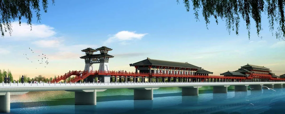 Bridge
Steel Structure Bridge System
Prefabricated steel truss and deck bridge systems for pedestrian, commercial and vehicular crossings. Bolted site connections, factory-controlled quality.
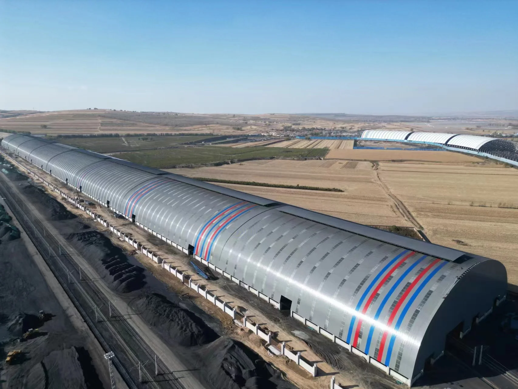 Envelope
Metal Roof & Wall Envelope
Profiled steel and sandwich-panel roofing, wall cladding and insulation systems that close the covered bridge against wind, rain and snow.
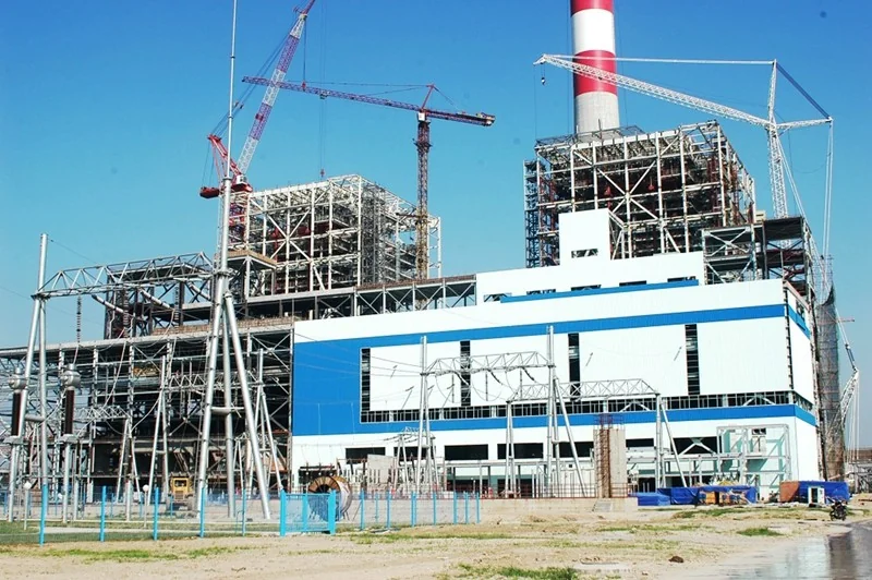 Components
CNC-Fabricated Steel Components
Shop-fabricated truss members, chords, gusset plates and connection components produced on our CNC lines with full traceability.
Planning a Bridge or Covered Structure?
From 748-meter covered bridges to pedestrian crossings, station canopies and covered commercial streets, our prefabricated steel truss-and-deck systems deliver factory-controlled quality, bolted-site erection and structures designed for 100-year service. Contact our engineering team to discuss your crossing.
Email: market@permanentsteelstructure.com | WhatsApp: +86 18621689980 | Phone: +86 516-83269982