
Ten Core Manufacturing Technologies: The Fabrication Science Behind Our Structures
Beyond the three core key technologies — intelligent design, intelligent manufacturing, and intelligent construction — Permanent Steel has developed ten specialized fabrication processes, each addressing a specific manufacturing challenge that arises in complex steel structure projects. These are not generic capabilities; they are patented or proprietary processes refined through project-specific engineering and validated on landmark structures including the 229-meter world-record grid and the Antarctic Ross Sea New Station.
Why These Technologies Matter
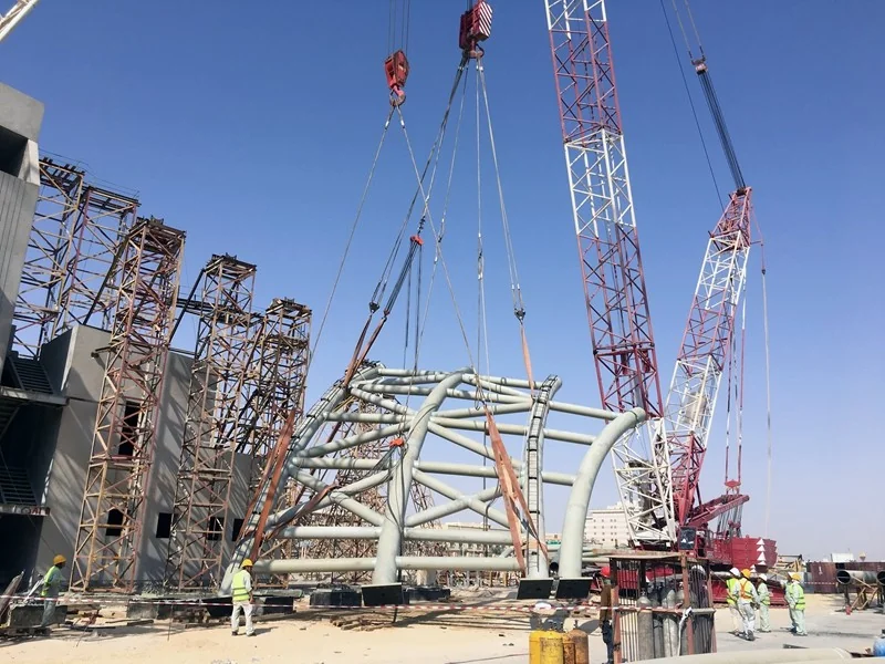
Steel structure fabrication is not a single process — it is a collection of specialized processes, each with its own technical challenges, quality requirements, and failure modes. A company that can cut and weld standard H-sections is not the same as a company that can fabricate a curved box truss with double-curved geometry, weld 60mm-thick plate without hydrogen cracking, or bend steel pipe to a precise radius while maintaining cross-sectional roundness. The ten technologies below represent the specific manufacturing competencies that differentiate Permanent Steel from commodity steel fabricators — the capabilities that enable us to execute projects that other manufacturers cannot.
Each technology was developed through a specific project requirement, refined through application on subsequent projects, and documented in our patent portfolio and technical publications. For each technology, the explanation below covers: what the technology is, why it matters (the engineering challenge it solves), and which landmark projects validated it in practice.
Ultra-long-span Steel Truss Fabrication
What it is: The fabrication of steel trusses with clear spans exceeding 200 meters — specifically, the manufacturing processes required to produce truss members and assemblies of such length that they cannot be transported as single pieces and must be fabricated in segments, transported separately, and assembled on site with full-strength connections that maintain the structural integrity of the continuous truss.
Why it matters: A 229-meter truss cannot be fabricated as a single piece — no factory, transport vehicle, or road network can accommodate a 229-meter-long steel assembly. The truss must be divided into segments, each fabricated to the required precision, transported to site, and connected with full-penetration welded or high-strength bolted splices that develop the full structural capacity of the continuous member. The engineering challenge is not just making the segments — it is ensuring that when the segments are connected on site, the resulting continuous truss behaves as designed, with accurate camber, alignment, and connection capacity.
Key technical considerations include: camber control (the truss must be fabricated with a pre-set upward curve so that under dead load it deflects to the design profile), thermal distortion management (welding shrinkage causes dimensional changes that must be predicted and compensated during fabrication), segment-to-segment fit-up (the connection geometry must match exactly, requiring precision fabrication or digital pre-assembly verification), and transport engineering (each segment must be designed for transport loads, which may differ from in-service loads).
Project validation: The 229-meter bolted-sphere grid coal storage facility — the world record for this grid type — validated this technology. The structure's trusses were fabricated in segments, transported to the remote project site, and assembled into a continuous structure spanning 229 meters without interior columns. The fabrication precision and segment connection methodology developed for this project are now applied as standard practice for all ultra-long-span truss projects.
H-shaped Truss with Complex Joints Fabrication
What it is: The fabrication of H-section steel trusses with joints where multiple members intersect at different angles — requiring intersecting curve cutting (profiling) on H-section ends, thick-plate welding at joint intersections, and precise assembly of complex three-dimensional connection geometry.
Why it matters: In a typical truss, members intersect at standard angles (45°, 60°, 90°) and the connection geometry is straightforward. In complex structures — where members converge at non-standard angles, where loading requires reinforced joint plates, or where architectural geometry dictates irregular member layouts — the joint fabrication becomes the most challenging aspect of manufacturing. The H-section end must be cut to a profile that matches the intersecting surface of the connecting member — not a simple straight or angle cut, but a complex curve defined by the intersection of two non-parallel, non-coplanar sections.
Permanent Steel's CNC cutting capability generates the intersecting curve profile directly from the design model and executes it with plasma or laser cutting to the required precision. The joint plates (gusset plates, stiffeners, connection plates) are cut and drilled by CNC equipment, and the assembly is welded using qualified procedures for thick-plate joints — often requiring preheat, interpass temperature control, and post-weld heat treatment to manage residual stresses and prevent cracking.
Project validation: Complex H-truss joints are a feature of many of our landmark projects, particularly structures with architectural geometry that requires non-standard member layouts. The fabrication methodology was developed through multiple project applications and is documented in our technical publications on steel structure joint design and fabrication.
Curved Box Truss Fabrication
What it is: The fabrication of box-section trusses with complex spatial curvature — trusses where the top chord, bottom chord, or both follow curved profiles in one or more planes, requiring the box section to be assembled from curved plate elements rather than straight-cut plates.
Why it matters: A straight box section is fabricated from four flat plates (top, bottom, two webs) welded along their edges. A curved box section requires each plate to be formed to the required curvature before assembly — and the curvature may be different for each plate (e.g., the top plate of a curved roof truss has a tighter radius than the bottom plate). The forming process (press braking, roller bending, or induction bending) must produce a smooth curve without local flat spots, buckling, or excessive thinning. The assembly of four curved plates into a closed box section requires precise positioning and clamping to maintain cross-sectional dimensions and straightness along the member's curved axis.
The challenge is compounded when the curvature is not constant along the member — a transition curve where the radius changes, or a compound curve where the member curves in two planes simultaneously. Each plate must be formed to its specific curvature profile, and the assembly must maintain the designed spatial geometry. Our parametric design model generates the forming instructions for each plate, and the fabrication process uses CNC-controlled forming equipment to achieve the required curvature.
Project validation: Curved box trusses are used in architecturally significant projects where the structural geometry follows curved architectural forms — stadium roofs, canopy structures, and curved bridge girders. The fabrication methodology was refined through multiple curved-box projects and represents a capability that few steel structure manufacturers possess at the precision and scale we achieve.
Steel Pipe & Profile Top-bending Fabrication
What it is: The cold bending of steel pipes and structural profiles to create curved members — arches, curves, and non-linear geometries — using CNC-controlled bending equipment that produces precise curvature while maintaining the cross-sectional shape of the member.
Why it matters: Bending a steel pipe is conceptually simple but practically complex. The bending process must produce the required radius without: ovalizing the cross-section (the pipe becomes elliptical rather than circular), wrinkling the inner radius (compression buckling on the concave side of the bend), thinning the outer radius (tensile stretching on the convex side), or producing local flat spots where the bending rollers contact the pipe. For structural applications, these defects are unacceptable — a pipe with 5% ovality may have significantly reduced buckling capacity compared to a perfectly round pipe.
Our self-developed hydraulic bending machine (shown among our production equipment) uses a mandrel-supported bending process for smaller pipes and a roller-bending process for larger profiles. The machine is CNC-controlled, with the bend radius, bend angle, and feed position derived directly from the design model. The machine can bend steel pipes from 60mm to 600mm diameter and structural profiles (H-sections, channels, angles) through various radii. For very large radii or compound curves, induction bending — which uses localized heating to reduce yield strength and enable bending with minimal residual stress — is employed.
Project validation: Bent steel pipes and profiles are used in arch structures, curved roof members, dome structures, and curved bridge girders across our project portfolio. The bending technology was developed for dome and arch grid structures where curved perimeter members are required, and has been applied in numerous sports venue and exhibition hall projects.
New Partially Encased Steel-Concrete Composite Structure Fabrication
What it is: The fabrication of Partially Encased Concrete (PEC) composite members — structural steel sections (H-sections, box sections, or built-up sections) with concrete cast into portions of the steel profile, creating composite members that combine the tensile strength of steel with the compressive strength and fire resistance of concrete.
Why it matters: PEC members are structurally efficient: the steel section carries tension and provides formwork for the concrete, while the concrete provides compression resistance, fire protection, and improved seismic performance. Compared to pure steel sections, PEC members achieve the same structural capacity with less steel tonnage — reducing material cost. Compared to reinforced concrete, PEC members are slimmer, lighter, and factory-prefabricated — reducing on-site construction time.
The fabrication challenge is in the manufacturing process: the steel section must be fabricated with internal elements (stud connectors, tie bars, diaphragms) that ensure composite action between steel and concrete, the concrete placement methodology must ensure complete filling without voids, and the curing conditions in the factory environment must be controlled to achieve the specified concrete strength. The steel section design must account for the construction stage (before concrete is cast, the steel section alone must support its self-weight and construction loads) and the composite stage (after concrete hardens, the combined section carries design loads). Our design model analyzes both stages, and the fabrication process is engineered to produce the composite member with the designed interface between steel and concrete.
Project validation: PEC composite structures are the basis of our System 03 (Low-carbon PEC Integrated Residential Building System) and are used in residential and low-rise commercial buildings where fire resistance, seismic performance, and construction efficiency are driving requirements. The fabrication methodology was developed through research at our Jiangsu Province Steel Structure Engineering Technology Research Center and validated through the joint research program with Shanghai Jiao Tong University.
Cross-shaped to Box-shaped Steel Column Fabrication
What it is: The fabrication of complex steel column sections built up from thick steel plates (40mm and thicker) — including cross-shaped columns (two or more plate elements assembled into a cross or star configuration) and box columns (four plates assembled into a closed rectangular or square section, often with internal diaphragms).
Why it matters: In multi-story and high-rise steel buildings, the columns carry the highest axial loads and must have the largest cross-sections. These columns are not rolled sections (no manufacturer rolls a 500mm×500mm×60mm box section) — they are built up from thick plates welded together. The fabrication challenges are significant: thick-plate welding requires preheat and interpass temperature control to prevent hydrogen cracking; the welding sequence must be carefully planned to minimize distortion (asymmetric welding of a box section will cause it to curve); internal diaphragms (transverse stiffeners inside the box) must be welded through access holes in the box walls, creating complex weld geometries; and the finished column must be straight, square, and dimensionally accurate to ensure it fits with the connecting beams and floor systems.
For cross-shaped columns, the challenge is welding the component plates together at their intersection — a T-joint or cruciform joint where the weld must develop the full strength of the connected plates. For thick plates (40mm+), full-penetration welds require multiple passes, with careful control of heat input to prevent distortion and cracking. Our thick-plate narrow-gap welding technology (Technology 08) is specifically used for these applications.
Project validation: Thick-plate box and cross-shaped columns are used in the primary structural frames of multi-story steel buildings (System 04) and in industrial structures with heavy equipment loads. The fabrication methodology has been applied in numerous building projects and represents a core capability for the high-rise steel building market.
Double-curved Beam & Spiral Staircase Fabrication
What it is: The fabrication of architecturally complex structural steel members that have double curvature (curving in two planes simultaneously) or helical geometry (spiral configurations) — including curved roof beams, spiral staircases, and free-form architectural steel.
Why it matters: Double-curved and helical members cannot be fabricated by standard bending processes, which produce single-plane curves. A double-curved beam requires the member to be formed in two directions simultaneously, or assembled from multiple curved components that are welded together. A spiral staircase stringer follows a helical path — the member curves in plan while simultaneously rising in elevation — requiring each segment to be fabricated with the precise compound angle and twist that matches the helical geometry. These members are typically one-of-a-kind fabrications, engineered for specific architectural designs, requiring a combination of CNC cutting, multi-axis forming, and skilled manual welding to achieve the designed geometry.
The fabrication process begins with the design model, which defines the double-curved or helical geometry mathematically. The model is decomposed into fabricable segments — each segment is a portion of the curve that can be produced by available forming equipment or assembled from cut plate elements. CNC cutting produces the plate elements with the required edge profiles; forming equipment produces the initial curvature; and skilled welders assemble the elements into the final member geometry, using templates and jigs to verify dimensional accuracy throughout the assembly process.
Project validation: Double-curved beams and spiral staircases are fabricated for architecturally significant projects where the structural steel is also a visual design element — grand staircases in public buildings, curved roof beams in signature structures, and sculptural steel elements. These fabrications demonstrate that Permanent Steel's capability extends beyond functional structural steel to the intersection of structural engineering and architectural artistry.
Thick-plate Narrow-gap Welding Technology
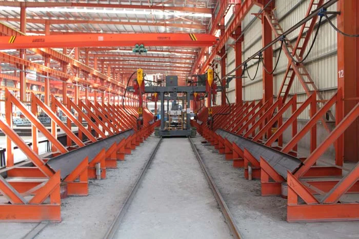
What it is: A specialized welding process for steel plates 40mm and thicker, using narrow-gap groove geometry (a narrow, deep V or U groove instead of the wide V groove used for thinner plates) to reduce weld volume, heat input, and distortion while maintaining full-penetration weld quality.
Why it matters: Welding thick steel plates is fundamentally different from welding thin plates. As plate thickness increases, the weld groove must be wider to allow the welding electrode to reach the root of the joint — but a wider groove means more weld metal, more heat input, longer welding time, and greater distortion. For a 60mm plate with a standard V-groove, the weld volume can be enormous — requiring many hours of welding and depositing many kilograms of weld metal, with each pass adding heat that distorts the member and creates residual stress.
Narrow-gap welding solves this by using a specially designed groove — typically a narrow U-groove with parallel or nearly-parallel walls — that reduces the weld cross-section by 50-70% compared to a standard V-groove. The narrow gap requires specialized welding equipment: a torch that can reach into the deep, narrow groove, with precise control of wire feed, voltage, and travel speed. The process typically uses submerged arc welding (SAW) or gas metal arc welding (GMAW) with oscillation to ensure sidewall fusion.
The benefits of narrow-gap welding for thick plates are: reduced weld volume (less consumable, less time), reduced heat input (less distortion, less residual stress, smaller heat-affected zone), and improved weld quality (narrower HAZ means better toughness in the weld region). The process requires careful procedure qualification to ensure complete fusion at the sidewalls — the narrow groove makes visual inspection of the root difficult, so ultrasonic testing is used to verify weld integrity.
Project validation: Narrow-gap welding is used for all thick-plate box and cross-shaped columns (Technology 06), for ultra-long-span truss joints (Technology 01), and for any application with plate thicknesses of 40mm or more. The welding procedure is qualified per Chinese standard GB 50661 and international standards (AWS D1.1, EN 1090), with mechanical testing of procedure qualification records including tensile, bend, and Charpy V-notch impact testing.
Ultra-low Temperature Service Structural Steel Welding
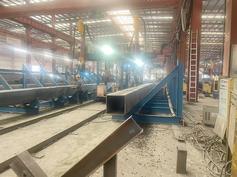
What it is: Welding procedures and processes developed specifically for structural steels that must maintain adequate toughness at service temperatures as low as -40°C to -60°C — conditions where conventional structural steels and welding procedures would produce brittle fracture.
Why it matters: Steel toughness decreases with temperature. At room temperature, structural steel is ductile — it deforms plastically before fracturing, providing warning of overload. At very low temperatures, the same steel may become brittle — fracturing suddenly with little or no plastic deformation, at stresses well below the material's yield strength. This transition from ductile to brittle behavior is the fundamental challenge of low-temperature structural steel design.
The welding process itself is the critical factor. Welding introduces a heat-affected zone (HAZ) where the base metal's microstructure is altered by thermal cycling. In the HAZ, grain growth and phase transformations can reduce toughness — making the HAZ the most likely location for brittle fracture initiation in low-temperature service. Welding procedures for ultra-low temperature service steel must be specifically engineered to: minimize HAZ grain coarsening (through controlled heat input), prevent hydrogen introduction (through low-hydrogen consumables and moisture control), produce a weld metal with toughness matching or exceeding the base metal at the service temperature, and avoid defects (cracks, porosity, lack of fusion) that act as brittle fracture initiators.
Permanent Steel's ultra-low temperature welding procedures are qualified through rigorous testing: Charpy V-notch impact testing at the service temperature (and at temperatures below it, for margin), CTOD (crack tip opening displacement) testing for fracture toughness, and hardness testing to verify that the HAZ does not exceed hardness limits. The procedures specify controlled preheat, interpass temperature, heat input limits, consumable selection (low-hydrogen electrodes with specific toughness ratings), and post-weld inspection requirements (100% ultrasonic testing, plus magnetic particle testing of the weld surface).
Project validation: This technology was developed specifically for the Antarctic Ross Sea New Station project — a scientific research station on the Antarctic continent where structural steel must withstand service temperatures as low as -60°C (and lower, with wind chill), extreme wind loads, and cyclic freezing-thawing. The project required not just low-temperature steel welding but a complete structural system designed for polar conditions — including material selection, connection design, coating systems, and construction methods suitable for Antarctic logistics. The successful fabrication and installation of this project's steel structure validated our ultra-low temperature welding capability under the most demanding service conditions any steel structure can face.
Digital Pre-assembly Technology for Steel Structures
What it is: A 3D digital twin-based virtual assembly process that verifies the fit-up of fabricated steel members before physical assembly — eliminating the need for physical trial assembly while providing the same or better fit-up verification.
Why it matters: Physical trial assembly — the practice of assembling a portion of the structure in the factory to verify that members fit together before shipping — has been standard practice for complex steel structures for decades. It catches fabrication errors, dimensional deviations, and interference issues before they reach the project site, where corrections are expensive and time-consuming. But physical trial assembly has significant costs: it requires factory floor space, crane time, and labor; it delays the shipping schedule; and for large structures, it is simply impractical — you cannot trial-assemble a 229-meter grid in a factory.
Digital pre-assembly replaces physical trial assembly with a 3D digital twin process. Each fabricated member is 3D-scanned (using laser scanners or photogrammetry) after fabrication, producing a point cloud or mesh model of the as-built member geometry. The as-built models are then assembled virtually in the 3D environment, matching the connection positions and orientations specified in the design model. The virtual assembly system checks: dimensional fit-up (do the members connect at the designed positions?), interference (do any members or connections physically intersect?), bolt hole alignment (do the bolt holes in connecting members align within tolerance?), and weld gap geometry (is the weld gap between members within the specified range?).
If the digital pre-assembly identifies a fit-up issue, the responsible member can be reworked in the factory before shipping — where corrections are cheap and fast. If no issues are identified, the members ship with digital pre-assembly verification, providing confidence that they will fit on site without the cost and delay of physical trial assembly.
The technology is particularly valuable for complex structures with many unique members — grid structures with thousands of nodes, structures with curved geometry where member-to-member fit-up is not straightforward, and projects with tight construction schedules where physical trial assembly time is a critical path constraint. For the 229-meter grid, digital pre-assembly was essential: physical trial assembly of a structure of that size was impossible, and the digital verification provided the confidence that on-site assembly would proceed without fit-up issues.
Project validation: Digital pre-assembly has been applied across our project portfolio for complex spatial structures, curved members, and projects with non-standard connection geometry. The technology was developed through our R&D program and represents the convergence of intelligent design (which produces the design model), intelligent manufacturing (which fabricates the members), and 3D scanning technology (which captures the as-built geometry). It was recognized in our Jiangsu Province Excellent Innovation Award for Construction Industry.
How These Technologies Work Together
No single manufacturing technology makes a steel structure project successful — it is the integration of multiple technologies, applied where each is needed, that produces the final result. A typical long-span grid project might use: ultra-long-span truss fabrication (Technology 01) for the main trusses, steel pipe top-bending (Technology 04) for curved perimeter members, thick-plate narrow-gap welding (Technology 08) for column connections, and digital pre-assembly (Technology 10) for fit-up verification — all within a single project, all executed under the intelligent manufacturing framework, and all engineered during the intelligent design phase.
What distinguishes Permanent Steel is not that we have one or two specialized fabrication capabilities, but that we have ten — developed through real project requirements, validated on landmark structures, and integrated into a coherent digital manufacturing workflow. This is the manufacturing depth behind the structures that have earned the Luban Prize and Steel Structure Gold Award. It is the fabrication science that enables us to build what others cannot.
Need a Specialized Fabrication Capability?
If your project requires fabrication processes beyond standard steel framing — ultra-long spans, thick-plate welding, curved geometry, or low-temperature service — our manufacturing engineers can evaluate the requirements and propose a qualified fabrication approach.