
Steel Structure Intelligent Manufacturing Technology
Core Key Technology #2. A self-developed intelligent production line that receives design data directly from the parametric design model, programs CNC equipment automatically, and tracks every member through the fabrication process with full digital traceability. 100,000m² of production workshops. 200,000 tons of annual manufacturing capacity. This is not a factory that follows drawings — it is a factory that is driven by data.
What Is Intelligent Manufacturing?
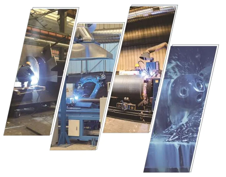
Traditional steel structure fabrication follows a paper-driven workflow: design drawings are printed, distributed to the shop floor, and interpreted by machine operators and welders. Each operator sets up their machine manually based on the drawing dimensions, fabricates the part, and marks it with a paint-stencil identification number. Production tracking is done by physical counting and manual data entry. Quality records are paper-based. When a problem is discovered during assembly, tracing it back to the specific machine, operator, and material batch that produced the defective part requires searching through physical records — if they exist at all.
Permanent Steel's intelligent manufacturing technology replaces this with a data-driven workflow. The parametric design model generates not only structural geometry but also manufacturing instructions: CNC cutting programs, welding procedure specifications, drilling coordinates, and assembly sequences. These instructions are transmitted directly to the shop floor's CNC equipment without human interpretation. Each fabricated member is tagged with a unique digital identifier (QR code or RFID), and its progress through every manufacturing station — cutting, drilling, welding, assembly, coating, inspection — is tracked in a real-time production management system. When a quality issue is identified, the system can trace any member back to its raw material batch, cutting machine program, welder certification, welding consumable lot, inspection record, and the exact time and station where it was processed.
This is the distinction between "using CNC machines" and "intelligent manufacturing." Many steel structure factories have CNC cutting machines and robotic welders. What makes manufacturing genuinely intelligent is the digital continuity from design to finished product — the absence of manual data re-entry, the presence of full traceability, and the real-time visibility of production status at every stage.
CAD-CAM Integration: Design Data Drives Production
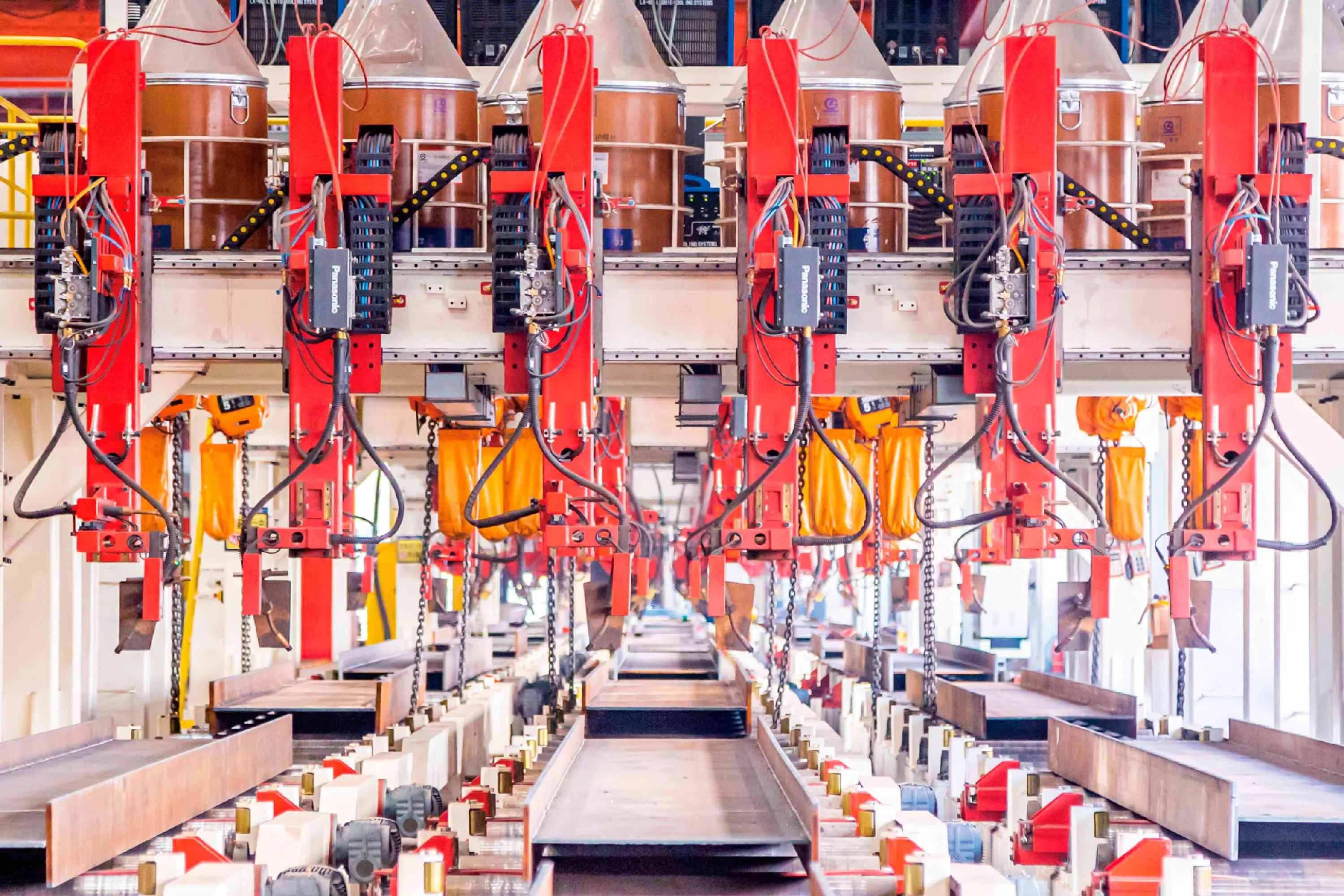
The intelligent manufacturing system's defining characteristic is the direct data pipeline from the intelligent design model to CNC production equipment. When the design engineer finalizes a grid structure model, the system automatically generates:
- CNC cutting programs for each member — the cutting path, feed rate, and torch parameters are derived directly from the member's cross-section and length in the design model, without manual nesting or program writing.
- Drilling programs for bolt-hole patterns — hole positions, diameters, and depths are extracted from the node design module and transmitted to CNC drilling machines.
- Welding procedure specifications (WPS) for welded connections — weld geometry, electrode type, current, voltage, and travel speed are determined by the joint type, material grade, and plate thickness from the design model.
- Assembly instructions — the sequence in which members are assembled into sub-assemblies is generated from the structural model's connectivity data.
- Coating specifications — surface area calculations, coating system type, and dry film thickness requirements are derived from the member's environment classification and exposure conditions.
At no point does a machine operator manually enter coordinates from a drawing into a CNC controller. The design model is the CNC program. This eliminates the most common source of fabrication errors: misreading of drawings, transposition of dimensions, and programming mistakes. If the design model is correct, the fabricated part is correct — because there is no human interpretation step between design and manufacturing.
This integration is particularly critical for spatial grid structures, where a single project may contain thousands of members with unique geometries. Programming each member's CNC instructions manually would require hundreds of hours of programmer time and would inevitably introduce errors. The automated data pipeline reduces this to minutes of processing time, with zero transcription errors.
CNC Plasma & Laser Cutting Technology
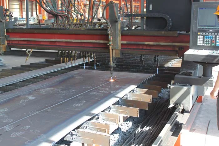
The first manufacturing station in the intelligent production line is CNC cutting. Steel plates and profiles arrive at the factory as raw material — standard-length plates, standard-section tubes, and standard-length bars. The cutting station transforms these into the individual members and components specified in the design model.
Our cutting capabilities include:
- CNC multi-torch straight cutting — multiple cutting torches operating simultaneously on a single plate, cutting multiple straight members in one pass. This is the highest-productivity method for rectangular members cut from plate steel. The machine shown at left represents this capability, with multiple torches cutting parallel lines simultaneously.
- CNC plasma cutting — for complex shapes, curves, and bevel cuts that straight cutting cannot produce. Plasma cutting uses a high-velocity jet of ionized gas to cut through steel, producing clean edges with minimal heat-affected zone. Our plasma systems handle plate thicknesses from 3mm to 80mm with positioning accuracy of ±0.5mm.
- CNC laser cutting — for high-precision components requiring tight tolerances and minimal edge cleanup. Laser cutting is used for complex connection plates, gussets, and components where plasma cutting's kerf and heat-affected zone would be excessive. Our laser systems achieve ±0.2mm positioning accuracy on plate up to 25mm thick.
- Bevel cutting — cutting edges at specific angles (V, X, K, Y grooves) to prepare weld joints. For thick-plate narrow-gap welding, the bevel geometry is critical to weld quality, and CNC bevel cutting ensures consistency across hundreds of joint preparations.
All cutting programs are generated automatically from the design model. When a plate arrives at the cutting station, the operator scans the digital work order, the CNC machine loads the appropriate cutting program, and the operator verifies material grade and thickness against the program parameters before cutting begins. The cut parts are immediately tagged with their digital identifiers, linking them to the design model for downstream tracking.
Robotic Welding & Automated Assembly
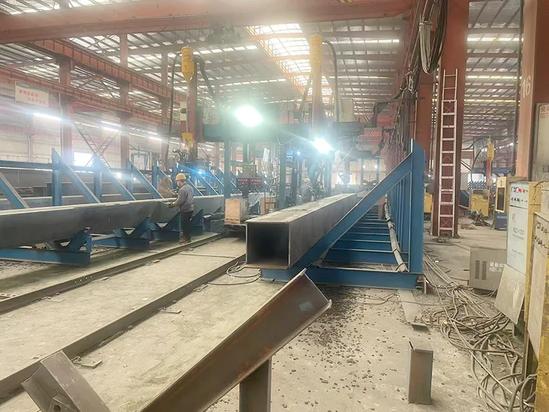
Welding is the most critical quality-determining process in steel structure manufacturing. A structurally perfect design with defective welds is a defective structure. Permanent Steel's welding capability combines robotic automation for repetitive, high-volume welds with manual welding by certified welders for complex, one-off joints — each governed by welding procedure specifications (WPS) generated from the design model.
Robotic Welding Stations
For high-volume, repetitive welding tasks — particularly the longitudinal welds on H-sections and box sections — robotic welding stations provide consistent quality and high productivity. The robot follows a pre-programmed path derived from the design model's joint geometry, maintaining precise control of travel speed, wire feed rate, voltage, and torch angle. Each weld is identical to every other weld of the same type, eliminating the variability inherent in manual welding. The system records welding parameters for each joint — current, voltage, travel speed, gas flow — creating a permanent quality record linked to the member's digital identifier.
Double-Wire Welding
For box-section fabrication, we use double-wire (twin-wire) submerged arc welding, as shown at left. This process uses two welding wires fed simultaneously through a single torch, depositing weld metal at approximately twice the rate of single-wire welding. The result is higher productivity for thick-plate box sections, with deeper penetration and lower heat input per unit of deposited metal — reducing distortion and residual stress in the fabricated member.
Submerged Arc Welding (SAW)
For thick-plate longitudinal welds on H-sections and box columns, submerged arc welding provides deep penetration, high deposition rate, and excellent weld appearance. The process uses a blanket of granular flux that covers the welding arc, protecting the molten weld pool from atmospheric contamination and producing welds with low hydrogen content — critical for ultra-low temperature service steel welding where hydrogen-induced cracking is a primary failure mode.
Welder Certification & Procedure Qualification
Every welder in our factory holds a valid welder qualification certificate for the specific welding process, position, and material type they are qualified to perform. Every welding procedure is qualified through a welding procedure qualification record (PQR) that includes mechanical testing of weld specimens (tensile, bend, impact, and hardness testing). These qualifications are not internal documents — they are available for client review and are maintained in the production management system, linked to every weld made under each procedure.
Automated Tube Cutting & CNC Drilling
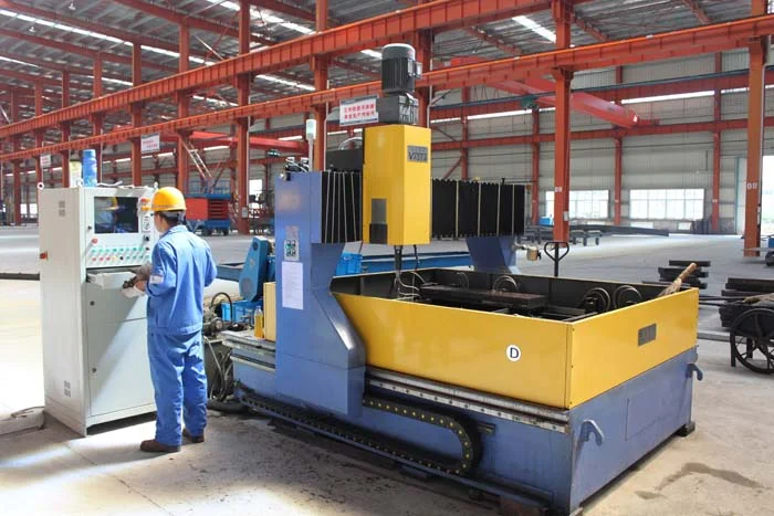
Grid structure members are predominantly steel tubes and pipes — circular hollow sections (CHS) and rectangular hollow sections (RHS). Processing these members requires specialized equipment that can cut, drill, and bevel tubular sections at specific angles and positions dictated by the node geometry in the design model.
CNC Tube Cutting
Our CNC tube cutting systems perform profile cutting on tubular members — cutting the ends of tubes at the precise angle and profile required to fit against the node sphere or connecting member. For bolted-sphere grid structures, each tube end must be cut square (perpendicular to the tube axis) and drilled with a bolt hole at the correct position. For direct-welded connections (welded-sphere grids, pipe trusses), the tube end must be cut to a complex intersecting curve profile that matches the surface geometry of the connecting member. This profile cut is generated directly from the design model's node geometry and executed by multi-axis CNC cutting.
CNC Drilling
The CNC plane drilling machine shown at left performs precision drilling of bolt holes in steel plates, flanges, and connection components. Hole positions, diameters, and depths are extracted directly from the design model and executed without manual layout. The machine can drill multiple holes in a single setup, maintaining positional accuracy of ±0.3mm across the drilling pattern. For grid structures, this is used for base plates, cap plates, and gusset plates where bolt-hole patterns must match the corresponding sphere or connection geometry exactly.
H-beam Production Line
For H-section members used in beam-string structures, industrial buildings, and multi-story steel frames, our intelligent H-beam production line performs automated assembly and welding of H-sections from three plates (web and two flanges). The line includes automatic plate positioning, tack welding, submerged arc welding (single or twin wire), and straightening — all driven by design model data. The line produces H-sections up to 1,500mm deep with web thicknesses up to 40mm and flange thicknesses up to 50mm, meeting the requirements of the most demanding steel structure applications.
Real-time Production Monitoring & Management System
The intelligent manufacturing system includes a real-time production monitoring and management platform that provides complete visibility of every member's status throughout the fabrication process. This is the digital nervous system of the factory — the system that makes "intelligent manufacturing" more than a collection of CNC machines.
Digital Work Order Management
Each fabricated member receives a digital work order that travels with it through the factory. The work order contains: the member's unique identifier, design model reference, material specification, cutting program, drilling program, welding procedure, coating specification, inspection requirements, and the intended assembly sequence. When the member arrives at a workstation, the operator scans its identifier and the work order is displayed on the station's terminal — no paper drawings, no manual lookups. The operator confirms material grade, performs the required operation, and the system records completion with timestamp, operator ID, and process parameters.
Real-time Tracking
The production management system displays real-time status of all work orders across all workstations — which members are at cutting, which are at welding, which are at coating, which are in inspection, and which are complete and ready for shipping. Project managers can see at a glance whether production is on schedule, which stations are bottlenecks, and which members are behind their planned completion date. This visibility enables proactive production management — identifying and resolving delays before they affect the delivery schedule.
Quality Traceability
Every quality-relevant event is recorded and linked to the member's digital identifier: material certificate number, cutting machine and program version, welder ID and welding parameters, inspection results (visual, dimensional, ultrasonic, magnetic particle), coating thickness measurements, and final acceptance status. If a quality issue is discovered during assembly on site — or years later during service — the system can retrieve the complete manufacturing history of any member in seconds. This level of traceability is not optional for structures in critical applications (infrastructure, energy facilities, public buildings); it is a contractual and regulatory requirement that our intelligent manufacturing system satisfies by design.
100,000m² Factory, 200,000-Ton Capacity
The intelligent manufacturing system operates within a 300+ mu (approximately 20 hectares) manufacturing base in Xuzhou, Jiangsu Province, with 100,000m² of enclosed production workshops. The workshops are organized into functional zones: raw material storage and preparation, cutting and drilling, welding and assembly, coating and finishing, finished goods storage, and shipping. The layout is designed for one-way material flow — material enters as raw steel at one end of the factory and exits as finished, coated, identified members ready for transport at the other end, minimizing handling and repositioning.
The annual manufacturing capacity of 200,000 tons makes Permanent Steel one of the largest steel structure manufacturers in China by tonnage. To put this in perspective: 200,000 tons of steel structures is sufficient to frame approximately 2-3 million square meters of industrial building floor area, or to construct the structural steel for 20-30 major long-span projects per year. This capacity is not just about tonnage — it is about the ability to handle multiple large projects simultaneously without compromising delivery schedules or quality standards on any individual project.
The annual construction capacity of 3,000,000m² — handled by our intelligent construction technology — represents the on-site assembly capability that complements the manufacturing capacity. Manufacturing 200,000 tons of steel is meaningless without the capability to erect it on site, and Permanent Steel's full-industry-chain model means both capabilities are under one organizational roof. The same company that designs and manufactures the structure is responsible for erecting it — providing single-point accountability that eliminates the finger-pointing that occurs when design, fabrication, and construction are handled by separate entities.
Digital Transformation of Construction Industrialization
Permanent Steel's intelligent manufacturing technology is recognized by the Jiangsu Provincial Government as a Demonstration Base for Construction Industry Modernization — a designation that identifies our factory as a reference standard for the transformation of construction from site-based craft work to industrialized factory production. This is the broader context in which intelligent manufacturing must be understood: it is not merely about using better machines in a steel structure factory; it is about redefining how buildings and structures are produced.
The digital transformation encompasses: design-to-manufacturing data integration (eliminating the drawing-to-machine data gap), production process digitization (replacing paper tracking with real-time digital tracking), quality management automation (replacing manual inspection records with sensor-based measurement and digital storage), and supply chain integration (linking material procurement, fabrication, and delivery scheduling in a single digital system). Each of these transformations reduces the time and error overhead inherent in traditional construction manufacturing.
For international clients, the practical implication is this: when you order a steel structure from Permanent Steel, you are not ordering from a workshop that will fabricate your members by hand from paper drawings. You are ordering from a digitally integrated manufacturing system that receives your design data, programs its CNC equipment automatically, tracks every member through production with full traceability, and delivers it with a complete digital quality record. The Special-Class Manufacturing qualifications we hold — for steel structures, bolted-sphere grid structures, and pipe truss structures — are the regulatory authorization that confirms our manufacturing capability meets the highest national standard for each structure type.
This digital quality record is not merely an internal management tool — it is deliverable documentation. When your structure ships, it arrives with a complete digital package: the manufacturing data for each member (CNC program version, material certificate, welder ID, welding parameters, inspection results, coating thickness), the as-built survey, and the nonconformance log documenting any deviations from design and their resolution. For international projects subject to independent third-party inspection (by SGS, TUV, Bureau Veritas, or equivalent), this documentation package streamlines the inspection process — inspectors can verify quality records against design requirements without re-inspecting every member. This reduces inspection time on site and accelerates project handover, which is particularly valuable for projects with tight construction schedules where every day of delay carries significant financial consequence.
Your Project, Fabricated with Intelligent Manufacturing
From design data to finished member, our intelligent production line delivers precision, traceability, and quality at industrial scale. Contact us to discuss your manufacturing requirements.