
Steel Structure Intelligent Construction Technology
Core Key Technology #3. A suite of construction methods for assembling complex spatial structures that cannot be erected with conventional crane-based approaches. Hydraulic jacking for large grid structures. Computer-controlled synchronous lifting for long-span roofs. Sliding installation for structures over occupied or sensitive spaces. Prestressed tensioning for beam-string systems. 3,000,000m² of steel structures assembled annually — not by stacking cranes, but by engineering the installation process with the same precision as the structure itself.
What Is Intelligent Construction?
Erecting a steel structure is straightforward when the structure is small and the site is open: a mobile crane picks up each member and sets it in place. But when the structure spans 229 meters, weighs thousands of tons, and must be assembled over an operating facility or in confined urban space, conventional crane-based installation becomes impossible. The crane cannot reach the center of a 229m span; the structure is too heavy for a single lift; the site cannot accommodate the crane footprint.
Intelligent construction technology replaces the "bigger crane" approach with engineered installation methods that use hydraulic systems, computer-controlled synchronization, and structural mechanics to assemble structures that no crane could handle. These methods are not improvised on site — they are designed as part of the intelligent design process, with the installation sequence, jacking forces, lifting capacities, and structural behavior during each construction stage analyzed and verified before any equipment is mobilized.
Permanent Steel holds Class-1 General Contracting for Building Construction and Class-1 Specialized Contracting for Steel Structure Engineering — the highest qualifications for construction execution in China. This means we are not merely a manufacturer that ships fabricated members to site for others to erect. We design the structure, manufacture the members, engineer the installation method, and execute the construction — with single-point accountability for the entire process. The intelligent construction technology described below is the methodological capability that makes this full-industry-chain model possible.
Hydraulic Jacking Technology for Large Grid Structures
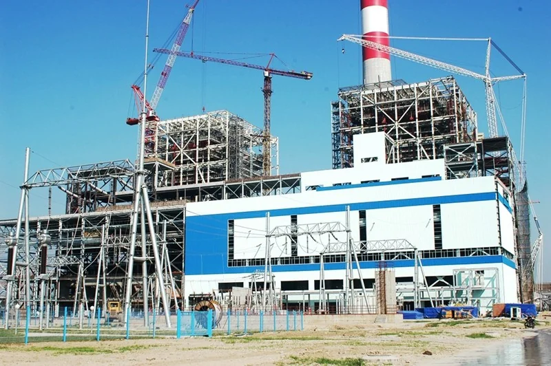
Hydraulic jacking is the primary method for erecting large spatial grid structures. The principle is to assemble the grid structure at ground level — where workers can access every node, every bolt can be torqued without scaffolding, and every weld can be inspected at eye level — and then lift the entire assembled structure (or large segments of it) into its final elevated position using hydraulic jacks mounted on support columns or temporary towers.
The advantages of ground-level assembly are significant: working conditions are safer and more controllable, productivity is higher (workers are not working at height or on temporary platforms), quality is better (bolts can be torqued accurately, welds can be inspected thoroughly), and the assembly schedule is shorter. The trade-off is the complexity of the lifting operation itself — which is where the intelligent construction technology earns its name.
How Hydraulic Jacking Works
The jacking system uses hydraulic cylinders installed at the top of the structure's support columns. Steel strands or rods are anchored to the grid structure at designated lifting points. The hydraulic cylinders pull the strands upward in synchronized strokes, lifting the grid in increments of 100-200mm per stroke. After each stroke, locking mechanisms hold the load while the cylinders retract for the next stroke. The process repeats until the grid reaches its final elevation, where it is permanently connected to the support structure.
For a 229-meter grid structure weighing several thousand tons, the jacking system may use dozens of hydraulic cylinders distributed across multiple support points. Each cylinder must lift its share of the total load, and all cylinders must advance at the same rate to prevent differential displacement that would distort the grid geometry. This is the core engineering challenge: not the lifting force (hydraulic cylinders can generate enormous force), but the synchronization.
Engineering Analysis of the Lifting Process
Before any jacking operation begins, the construction sequence is analyzed in the intelligent design model. At each construction stage — ground assembly, initial lift, intermediate lift positions, final connection — the structural behavior of the grid is analyzed using FEA. The analysis verifies that: the grid can support its own weight during lifting without exceeding member capacity; the lifting point forces do not overload the local node connections; the temporary support structure (jacking towers, temporary brackets) has adequate capacity; and the differential displacement tolerance between lifting points is maintained.
Computer-Controlled Synchronous Lifting
For structures with multiple lifting points distributed across a large area, maintaining synchronization between lifting points is the critical safety and quality control challenge. If one lifting point advances faster than others, the structure's geometry distorts, creating internal forces that were not analyzed in the design model. In extreme cases, differential lifting can cause structural failure during construction.
Permanent Steel's computer-controlled synchronous lifting system solves this problem through real-time monitoring and feedback control. The system architecture includes:
- Position sensors at each lifting point — laser distance meters or encoder-based stroke sensors that measure the vertical position of each lifting point with millimeter-level accuracy, updated multiple times per second.
- Load cells at each hydraulic cylinder — measuring the force exerted by each cylinder in real time, ensuring that no lifting point exceeds its designed load capacity.
- Computer control system — a central controller that receives position and load data from all lifting points, compares actual positions against the target lift trajectory, and adjusts hydraulic flow to each cylinder to maintain synchronization. The system can maintain position synchronization of ±5mm across lifting points separated by more than 200 meters.
- Safety interlocks — automatic stop conditions that halt the entire lifting operation if any lifting point deviates beyond its tolerance, if any cylinder exceeds its load limit, or if hydraulic pressure drops (indicating a potential system failure). The system fails safe — locking the load in place and alerting operators to investigate before resuming.
The synchronous lifting system is what makes it possible to erect a 229-meter grid as a single piece (or as a few large segments) rather than member-by-member at height. Without computer-controlled synchronization, the differential forces across such a large structure would be unmanageable — the structure would distort during lifting, and the internal forces generated by that distortion could damage connections designed for the in-service load condition, not the construction-stage condition.
This technology was recognized with the 1st Prize in Science & Technology Progress & Technology Innovation from the China Steel Construction Society — specifically for innovations in synchronous lifting control methodology for spatial steel structures.
Sliding Installation for Long-span Roofs
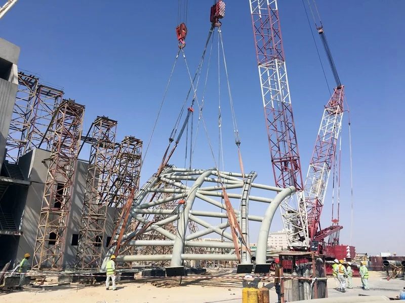
Sliding installation (also called incremental launching or sliding roof construction) is used when a long-span roof structure must be installed over an existing or simultaneously constructed facility where crane access is impossible or where the space below the roof must remain operational during construction. Examples include: airport terminal roofs (where the terminal below must remain operational), sports arena roofs (where the playing field below cannot support crane loads), and industrial facility roofs (where production cannot be interrupted for construction).
How Sliding Installation Works
The roof structure is assembled in a staging area at one end of the building — typically on the ground or on a temporary platform at roof level. The assembled roof segment is then pushed or pulled along sliding tracks installed on the building's support columns, moving it into its final position. As each segment reaches its position, the next segment is assembled in the staging area and connected to the previous segment, and the combined structure is slid further into position. The process repeats until the entire roof is in place.
The sliding system uses PTFE (Teflon) sliding bearings or roller bearings installed on the support columns, with hydraulic push-pull cylinders providing the motive force. The sliding resistance of a steel roof on PTFE bearings is typically 2-4% of the vertical load — meaning a roof weighing 1,000 tons requires 20-40 tons of horizontal force to slide, well within the capacity of hydraulic cylinders. The sliding speed is controlled to 0.5-2.0 meters per hour, with continuous monitoring of bearing reactions, sliding track alignment, and structural behavior during each sliding increment.
Engineering Considerations
Sliding installation introduces structural loading conditions that do not exist in the completed structure. During sliding, the roof is supported only at the sliding track locations — not at the final support positions. This changes the support reaction distribution and may create bending moments and shear forces that exceed the in-service values. The intelligent design model analyzes each sliding stage, verifying that the structure can support itself in every intermediate sliding position, that the cantilevered portion of the roof (the leading edge that has left the staging area but not yet reached the far support) does not exceed deflection or stress limits, and that the sliding bearings have adequate capacity for the reaction forces at each support point.
Sliding installation was used for the Guangzhou Baiyun International Airport Terminal Phase III roof, where the long-span steel roof was assembled at one end of the terminal and slid into position over the operational terminal below — a construction method that allowed the airport to remain fully operational during roof installation.
Prestressed Tensioning for Beam-string Structures
Beam-string structures (System 02 in our technology systems) rely on prestressed high-strength steel cables to provide mid-span support to the compression beam. The cables are installed in a slack (unstressed) condition and then tensioned to a specified force using hydraulic jacks. The tensioning process is itself a critical construction operation — the cable force must be applied in a controlled sequence, with continuous monitoring of cable force, beam deflection, and structural behavior.
The Tensioning Sequence
In a beam-string structure with multiple cables, the cables cannot be tensioned independently — tensioning one cable changes the force distribution in all others. The tensioning sequence must be engineered: which cables to tension first, how much force to apply in each increment, and how many passes are required to reach the target prestress. The intelligent design model computes the tensioning sequence, specifying the jack force and sequence for each cable at each tensioning stage.
Monitoring During Tensioning
During tensioning, the following parameters are monitored in real time: cable force (measured by load cells on the hydraulic jacks and by cable force transducers), beam deflection (measured by surveying instruments or LVDTs), and strut compression (measured by strain gauges or load cells). The measured values are compared against the design model's predicted values at each tensioning stage. Significant deviations indicate either a construction error or a design model inaccuracy that must be investigated before proceeding.
The target prestress force is not simply a fixed value — it depends on the dead load present at the time of tensioning, the expected live load, thermal effects, and long-term relaxation of the cable and anchors. The design model computes the required initial prestress to achieve the target structural performance under the full design loading, accounting for all losses (cable relaxation, anchor seating, elastic shortening of the structure, creep and shrinkage of any concrete elements).
Why This Matters
An improperly tensioned beam-string structure is not merely underperforming — it is potentially unsafe. Under-tensioning means the cable does not provide adequate mid-span support, overloading the beam. Over-tensioning means the cable force exceeds the beam's capacity to resist the induced upward force, potentially causing beam instability. The intelligent construction technology ensures that the tensioning is executed precisely as designed, with real-time verification at every stage.
3D Surveying & As-built Verification
Before, during, and after construction, Permanent Steel performs 3D surveying using total stations, laser scanners, and GPS-RTK systems to verify that the as-built structure matches the design model. This is not a perfunctory final check — it is an integral part of the intelligent construction process.
Pre-construction Survey
Before construction begins, the support structure (concrete columns, foundations, abutments) is surveyed to verify that support point positions, elevations, and anchor bolt patterns match the design model within specified tolerances. Discrepancies are identified and corrected before any steel is erected — adjusting a concrete column by 20mm is far cheaper than fabricating a custom steel adapter after the structure arrives on site.
During-construction Monitoring
During lifting, sliding, and tensioning operations, key structural points are continuously monitored for position, deflection, and alignment. The monitoring data feeds back into the construction control system, allowing real-time adjustment of lifting forces, sliding speeds, and tensioning sequences based on measured structural response rather than theoretical predictions alone.
As-built Verification
After construction is complete, the entire structure is surveyed and the as-built geometry is compared against the design model. Member positions, connection orientations, deflections under dead load, and overall structural geometry are verified against specification. The as-built survey becomes part of the project quality record and serves as the baseline for future structural health monitoring.
Safety Monitoring During Construction
Steel structure construction involves inherent risks: heavy lifts, work at height, temporary instability during assembly, and exposure to wind and weather. Permanent Steel's intelligent construction technology includes a comprehensive safety monitoring framework that is integrated into every construction method:
- Wind monitoring — anemometers installed at the lifting elevation provide real-time wind speed data. Lifting operations are suspended when wind speed exceeds the project-specific limit (typically 8-10 m/s for crane operations, potentially higher for hydraulic jacking systems that are less wind-sensitive). The system also monitors wind direction, as certain structure geometries are more sensitive to wind from specific directions.
- Structural health monitoring — strain gauges and displacement transducers installed at critical structural points during construction provide real-time data on stress and deformation. If measured values approach pre-set thresholds (typically 80% of design values), the system alerts the construction team to stop and investigate before proceeding.
- Temporary structure monitoring — jacking towers, temporary supports, sliding tracks, and falsework are monitored for settlement, deformation, and load. Temporary structures fail more frequently than permanent structures, and continuous monitoring is essential.
- Personnel safety systems — fall protection, confined space monitoring, and access control ensure that workers are not exposed to uncontrolled risks during complex construction operations. The safety protocols are project-specific, developed during the construction method engineering phase.
Our Luban Prize and Steel Structure Gold Award recognitions include assessment of construction safety management — award-winning projects must demonstrate not only quality of the finished structure but also safe execution of the construction process. The safety monitoring framework is an integral part of that assessment.
3,000,000m² Annual Construction Capacity
Permanent Steel's annual construction capacity of 3,000,000m² represents the on-site assembly capability that complements our 200,000-ton manufacturing capacity. This capacity is enabled by multiple construction teams operating simultaneously across different project sites, each equipped with the hydraulic jacking, synchronous lifting, sliding, and tensioning systems described above.
The construction capacity is backed by our Class-1 General Contracting for Building Construction and Class-1 Specialized Contracting for Steel Structure Engineering qualifications — the highest construction execution qualifications in China. These qualifications authorize us to serve as the general contractor for building construction projects, meaning we can manage not only the steel structure installation but also the coordination with concrete, mechanical, electrical, and other construction trades. For clients seeking a single-point-of-contact delivery model — from design through construction to handover — Permanent Steel is one of the few Chinese steel structure manufacturers with the full qualification chain to deliver it.
Our construction portfolio includes landmark projects: the Antarctic Ross Sea New Station (requiring ultra-low temperature service steel welding and construction in polar conditions), the Guangzhou Baiyun International Airport Terminal Phase III (sliding roof installation over an operational airport), the 229-meter world-record coal storage grid, and dozens of sports venues, exhibition centers, industrial facilities, and infrastructure projects across China and internationally. Each project's construction method was engineered specifically for its site conditions, structural geometry, and operational constraints — demonstrating that intelligent construction is not a single method but a methodology: the systematic engineering of the installation process, adapted to the specific demands of each individual project.
Need a Construction Method for a Difficult Site?
Our construction engineering team can evaluate your site conditions, structural requirements, and operational constraints to develop a tailored installation method. From hydraulic jacking to sliding installation, we engineer the construction process as carefully as the structure itself.