
Guangzhou Baiyun International Airport Phase III
One of China's busiest aviation hubs, expanded with a large-span steel roof grid that provides column-free concourse space for tens of millions of annual passengers. The terminal roof required a spatial grid structure engineered for seismic resilience, wind uplift, and integration with complex mechanical, electrical, and plumbing systems — all while maintaining the architectural vision of a soaring, light-filled space.
| Project Type | International airport terminal roof expansion |
|---|---|
| Location | Guangzhou, Guangdong, China |
| Structural System | Large-span spatial grid roof with redundant load paths |
| Key Dimensions | Column-free roof span above 80 m; grid depth optimized for deflection, MEP routing and architectural clearance |
| Steel Quantity | Available on request from project records |
| Supply Scope | Steel roof structure supply and fabrication; MEP penetration coordination and erection support as required |
| Design Basis | Critical-infrastructure seismic performance, wind uplift checks, deflection control and GB fabrication acceptance practice |
| Installation / Logistics | Complex roof zones require coordinated lifting, temporary bracing and MEP integration; schedule available on request |
| Client / Completion Year | Available on request; public project identity shown without unsupported client claims |
Need exact tonnage, installation schedule, crane plan or container count for a comparable project? Request a technical quote and send your drawings or sketch.
Expanding China's Southern Gateway
Guangzhou Baiyun International Airport is among the world's busiest airports by passenger traffic. The Phase III expansion was undertaken to accommodate surging demand in the Greater Bay Area economic zone, adding terminal capacity, concourse gates, and processing infrastructure for both domestic and international operations.
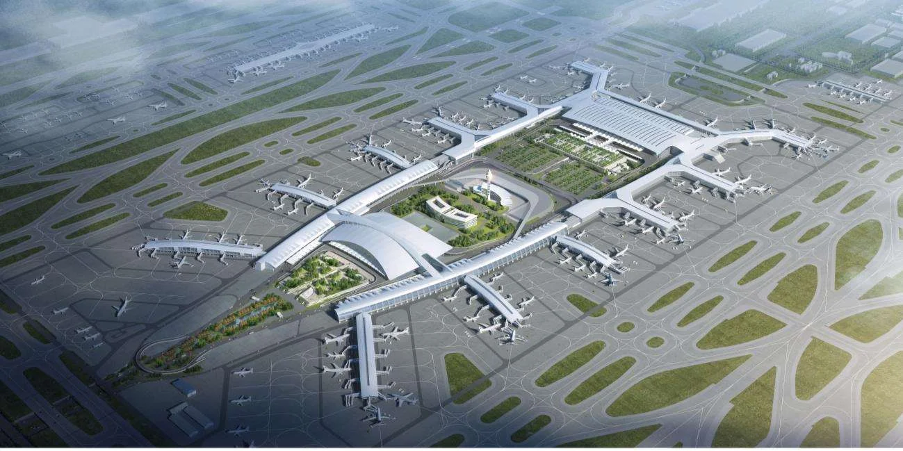
Permanent Steel was contracted to supply and fabricate the steel structure for the Phase III terminal expansion. The project's structural system centers on a large-span spatial grid structure roof that achieves column-free spans exceeding 80 meters across the main concourse. This span allows the terminal interior to remain open and unobstructed — essential for passenger flow, retail operations, and the visual impression of space that defines a modern international gateway airport.
The choice of a spatial grid structure for the roof was driven by several converging requirements. First, the span: a 80 m column-free span is well beyond the practical range of conventional beam-and-column steel framing, which typically tops out at 18-24 m without intermediate columns. A spatial grid, by distributing forces through a three-dimensional network of members, can achieve this span with a depth-to-span ratio of approximately 1:12 to 1:15 — meaning a 80 m span can be achieved with a grid depth of only 5-7 meters, keeping the roof profile low and the interior volume manageable from both an architectural and an HVAC perspective.
Second, the grid structure provides inherent redundancy. In a conventional truss, the failure of a single critical chord member can trigger progressive collapse of the entire span. In a three-dimensional grid, loads redistribute through multiple parallel paths; the loss of one member reduces overall capacity but does not trigger catastrophic failure. This redundancy is not merely a structural nicety — for an airport terminal classified as critical infrastructure, it is a life-safety requirement. The building must survive a design-level earthquake without partial collapse, because the evacuation of thousands of passengers depends on the roof staying in place.
Guangzhou: A Seismic Context
Guangzhou is located in a region of moderate seismic hazard, with a design basic earthquake acceleration of 0.10g (seismic intensity 7 on the Chinese scale) per GB 50011. While this is not the highest seismic zone in China, the criticality classification of an airport terminal means that the structural performance objectives are elevated beyond standard building requirements. The terminal must not merely survive a design earthquake — it must remain functional after one, because the airport serves as a critical lifeline facility for post-earthquake emergency response, evacuation, and relief operations.
This elevated performance objective is categorized as "performance level 2" or "operational" under the Chinese seismic performance-based design framework (GB 50011, Appendix M). It means that under the rare earthquake (the maximum considered earthquake with a 475-year return period for this region), the structure must suffer only minor damage — essentially elastic response with controlled, repairable cracking in non-structural elements, and no yielding of primary structural members that would compromise post-event operability.
Engineering an Airport Terminal Roof
1. Large-Span Roof Deflection Control
A roof spanning 80+ meters must satisfy not only strength requirements but also serviceability limits. The deflection of a long-span roof under dead and live loads affects the performance of everything suspended from or attached to it: ceiling systems, curtain wall supports, baggage handling rails, lighting tracks, HVAC ductwork, and fire suppression piping. A roof that deflects 150 mm at mid-span — well within structural code limits — can cause a rigid ceiling system to crack, a glazing support to fail, or a drainage slope to reverse.
The challenge was compounded by the asymmetric geometry of the terminal roof. Airport terminal roofs are rarely simple flat rectangles; they incorporate skylight bands, curved leading edges, varying overhangs, and differential heights to create architectural interest and manage daylighting. These geometric variations produce non-uniform load paths, where some grid zones carry significantly more load per unit area than others. The grid design had to be optimized: member sizes varied by zone, with heavier sections in high-load areas and lighter sections where load was reduced, achieving material efficiency without sacrificing deflection control.
2. Wind Uplift on a Large Roof Area
An 80 m span roof presents a enormous windward and suction area. Wind tunnel testing and CFD analysis were required to determine the wind pressure distribution across the roof's complex geometry. The critical load case for the roof structure was frequently not downward gravity load but upward wind suction — the force that attempts to peel the roof upward from its supports.
Wind uplift creates a reversal of forces in the grid structure. Members that are designed as compression members under gravity load suddenly experience tension under wind suction, and vice versa. Bolted connections that were designed for shear under gravity load must now resist direct tension. The connection design had to account for this force reversal, ensuring that every bolted joint in the grid could perform in both directions without capacity loss.
3. MEP Integration and Penetrations
A modern airport terminal is as much a mechanical plant as it is a building. The roof structure supports or accommodates:
- HVAC systems: Large-diameter ductwork (1-2 m diameter) routing conditioned air to dozens of air handling units distributed across the concourse
- Lighting: Architectural lighting, runway approach lighting support, and emergency lighting systems
- Fire protection: Sprinkler mains, fire pump connections, and smoke evacuation systems
- Baggage handling: In some terminal configurations, baggage conveyor rails are suspended from the roof structure
- Passenger boarding bridges: The structural support points for boarding bridge connections to the terminal
Each of these systems requires penetrations through the grid structure, support brackets attached to grid members, and hanging loads that add to the dead load. The structural design had to coordinate with the MEP design at the member level — not merely at the zone level. A grid member selected to support a 2-tonne air handling unit cannot simply be "beefed up" without checking the knock-on effects on the rest of the grid's load distribution. This coordination is where a steel structure fabricator's engineering depth matters as much as their manufacturing capacity.
4. Seismic Performance of Long-Span Roofs
Long-span roofs behave differently from conventional floor structures under seismic loading. Their long natural periods (typically 1-3 seconds) place them in the displacement-sensitive rather than acceleration-sensitive range of the response spectrum. This means that the roof itself may not experience large accelerations, but it will experience large relative displacements with respect to its supports. The differential movement between the roof and the supporting columns must be accommodated by the connection design — typically through connections that allow controlled sliding or rotation to prevent the buildup of forces that would damage either the roof or the columns.
Additionally, vertical seismic components (which are typically neglected in conventional building design) can be significant for long-span roofs. A roof spanning 80 meters responds to vertical ground motion much more dramatically than a 6-meter floor span, because the roof's vertical natural period is closer to the dominant frequencies of vertical ground motion. The grid structure's vertical seismic capacity had to be explicitly checked.
Design and Fabrication Approach
Spatial Grid Optimization
The roof grid was designed using a bolted-sphere spatial grid system — a system in which steel members connect to forged steel nodes (spheres) via high-strength bolts threaded into the node. This system, central to our spatial grid structure product line, offers several advantages for airport terminal applications:
- Factory prefabrication of nodes: The bolted spheres are machined in the factory with pre-drilled, pre-threaded connection points at precise angles. Field assembly involves bolting members to spheres — no field welding of primary structural connections.
- Member standardization: Members can be produced in standard lengths and section sizes, with non-standard members only where geometry demands. This reduces fabrication cost and simplifies quality control.
- Connection inspection: Bolted connections are inspectable by torque verification and visual examination, without the radiographic or ultrasonic testing required for welds. This speeds both fabrication and field acceptance.
- Force reversal tolerance: The bolted sphere connection resists both tension and compression, which is critical for the wind uplift load case where member forces reverse.
Member sizing was optimized through iterative structural analysis. The grid was modeled in structural analysis software, and each member was checked for the governing load combination (gravity, wind uplift, seismic, and combinations thereof). Members were then assigned section sizes from our standard range, with larger sections where forces demanded and smaller sections where forces permitted. This optimization process, repeated across hundreds of members, achieves a steel tonnage that is typically 15-25% lower than a uniform-section grid of equivalent capacity — a significant saving on a roof of this scale.
Seismic Connection Design
The connections between the roof grid and the supporting columns were designed as seismic isolation joints — connections that accommodate relative displacement between the roof and columns during an earthquake without transferring damaging forces to either element. This involved:
- Slotted bolt holes: Elongated holes that allow the connection to slide a controlled distance (typically 50-100 mm) before engaging bearing resistance, dissipating seismic energy through friction
- Yielding fuse elements: Specially designed plates that yield in a controlled manner at a predetermined force level, absorbing seismic energy and protecting the primary grid structure
- Vertical isolation: Flexible bearing pads at the column-roof interface that decouple vertical seismic input from the roof structure
Fabrication Quality and Erection Sequencing
The grid was fabricated in our Xuzhou facility, with all bolted spheres machined to tolerance and all members cut to length with CNC precision. Member end plates were fabricated with pre-drilled bolt holes matched to the sphere node geometry. The entire grid was trial-assembled in the factory in sections to verify geometric compatibility before shipment — a quality control practice that catches fabrication errors in the factory rather than on the construction site.
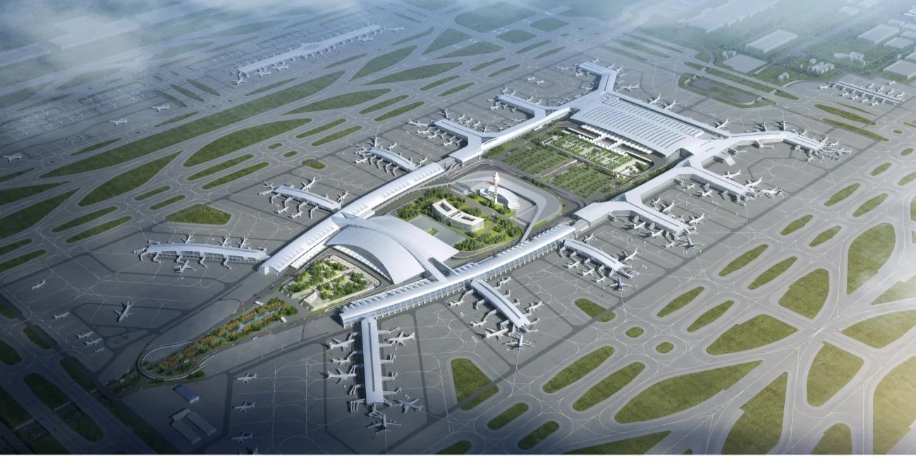
Erection sequencing was planned to manage the progressive loading of the structure as grid sections were installed. A long-span grid cannot be simply lifted into place as a single unit; it is assembled section by section, with temporary shoring towers supporting the partially completed structure until the grid achieves self-supporting geometry. The sequencing had to account for the crane access, the structural capacity of partially completed grid sections, and the wind loads that the partially erected structure would face during the construction period.
Deflection Monitoring During Construction
During erection, the grid's deflection was monitored at critical points using survey instruments. The predicted deflection under self-weight was compared to the actual measured deflection as each section was installed. Any deviation exceeding 15% of the predicted value triggered an engineering review before further erection proceeded. This real-time verification ensured that the as-built structure matched the as-designed model, and that any fabrication or erection discrepancies were identified and corrected before they compounded.
Pre-camber was built into the grid fabrication. The grid was fabricated with a slight upward curvature (camber) equal to the predicted dead-load deflection, so that under permanent dead load the grid settles to the design (flat) position. Without pre-camber, the grid would permanently sag under its own weight, creating drainage issues and aesthetic problems. The pre-camer value, calculated from the structural model, was built into the member lengths and node positions during factory fabrication.
Critical Infrastructure, Proven Capability
Airport terminals are among the most demanding steel structure projects a fabricator can undertake. They combine large spans, complex geometry, critical-infrastructure seismic requirements, intense MEP coordination, and aggressive construction schedules driven by airline opening dates. The Guangzhou Baiyun Airport Phase III project demonstrated Permanent Steel's capability to deliver on all these dimensions simultaneously.
The project also demonstrated the value of the bolted-sphere spatial grid system for large-roof applications. The system's factory prefabrication, field bolted assembly, and bidirectional force capacity make it ideally suited to projects where the roof structure must span large distances, accommodate complex geometry, and resist multi-directional loads — all while meeting aggressive construction timelines.
For the Greater Bay Area, the expanded terminal increased the airport's capacity to serve the economic integration of Guangdong, Hong Kong, and Macau. The structural steel that Permanent Steel fabricated supports the daily passage of hundreds of thousands of travelers — a responsibility that we take as seriously as the engineering calculations behind every member.
Systems Used in This Project
 Structure
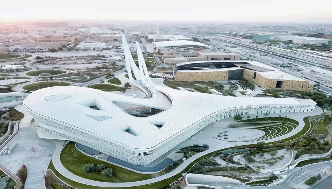
Bolted-Sphere Grid Structure
Factory-prefabricated nodes with bolted member connections. Ideal for large-span roofs requiring rapid field assembly and bidirectional force capacity.
Envelope
Metal Roof Envelope System
Standing seam metal roofing with integrated insulation, vapor barrier, and daylighting. Designed for airport terminal roof performance.
 Components
Steel Structure Components
Precision-fabricated steel members, connection plates, and support brackets. CNC-cut, trial-assembled, and quality-verified before shipment.
Planning a Large-Span Roof Project?
Whether it is an airport terminal, exhibition center, stadium, or industrial facility, our spatial grid structure systems can achieve spans up to 100+ meters with factory-prefabricated, field-bolted assembly. Contact our engineering team to discuss your project requirements.
Request a Consultation WhatsApp Our Engineer