
Xuzhou High-Speed Railway Station
A 75,000 m² station building — 130 m wide, 228.5 m long, with a maximum column-free span of 75 meters — crowned by an orthogonal square-pyramid grid structure roof. Our home city's flagship station on China's national high-speed rail network, and a live demonstration of our grid structure manufacturing capability visible to every factory visitor.
| Project Type | High-speed railway station concourse roof |
|---|---|
| Location | Xuzhou, Jiangsu, China |
| Structural System | Orthogonal square-pyramid spatial grid roof |
| Key Dimensions | Approx. 75,000 m² station building; 130 m wide, 228.5 m long; maximum 75 m clear span |
| Steel Quantity | Available on request from project records |
| Supply Scope | Steel roof grid fabrication, CNC member production, coating preparation and erection support |
| Design Basis | Chinese steel, seismic and fabrication acceptance practice; member and connection details available for comparable projects |
| Installation / Logistics | Sectional assembly, temporary shoring, progressive closure and controlled shoring removal; schedule depends on site crew and crane plan |
| Client / Completion Year | Available on request; public project identity shown without unsupported client claims |
Need exact tonnage, installation schedule, crane plan or container count for a comparable project? Request a technical quote and send your drawings or sketch.
The Station at the Crossroads of China
Xuzhou is one of China's most important railway junctions — the point where the Beijing-Shanghai and Longhai (Lanzhou-Lianyungang) mainlines intersect. The high-speed railway station serves this junction, connecting Xuzhou to Beijing, Shanghai, and dozens of intermediate cities at speeds of 250-350 km/h.
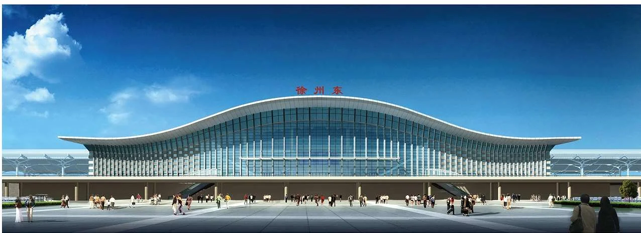
The station building covers approximately 75,000 m² of total floor area, with main concourse dimensions of 130 meters in width and 228.5 meters in length. The most striking structural feature is the maximum column-free span of 75 meters — achieved using an orthogonal square-pyramid grid structure. This span creates an open, column-free concourse that accommodates ticketing, waiting areas, retail, and passenger circulation without intermediate structural columns interrupting sightlines or circulation paths.
The choice of a square-pyramid grid structure was driven by the specific requirements of a high-speed rail station roof. The structure must span a large distance (75 m) while supporting significant dead and live loads, maintaining deflection control for suspended mechanical and ceiling systems, and providing the architectural expression appropriate for a major public building. The square-pyramid grid — a spatial grid in which the grid pattern forms alternating upward and downward pyramids — provides an efficient depth-to-span ratio and a visually rich structural rhythm that serves as an architectural feature in its own right.
What Is a Square-Pyramid Grid?
A square-pyramid grid structure, also known as a square-on-square offset grid, is a spatial grid in which the top and bottom chord layers are both arranged in square patterns, but the bottom layer is offset by half a module from the top layer. This offset creates a three-dimensional pattern of alternating upward-pointing and downward-pointing pyramids — each bottom chord node sits at the center of a square formed by four top chord nodes, and each top chord node sits at the center of a square formed by four bottom chord nodes.
This geometry has several structural advantages:
- Efficient load distribution: Each load point is connected to four members above and four members below, creating a highly redundant load path network. Redundancy means that the failure of any single member redistributes load through alternative paths without progressive collapse — a critical safety characteristic for public buildings with high occupancy.
- Uniform member forces: In a well-proportioned square-pyramid grid, the member forces are relatively uniform across the structure, allowing standardization of member sizes. This reduces fabrication complexity and cost compared to grids with highly variable member forces.
- Architectural expression: The alternating pyramid pattern creates a visually rhythmic underside that serves as an architectural ceiling feature — a textured surface that plays with light and shadow, eliminating the need for a separate suspended ceiling in the concourse areas.
- Service integration: The depth of the grid structure provides natural void space for mechanical, electrical, and plumbing (MEP) services — ductwork, lighting, sprinkler piping, and communications cabling can be routed within the grid depth, hidden from view while remaining accessible for maintenance.
The "orthogonal" descriptor means that the grid members are aligned with the principal axes of the building — parallel to the length and width of the station. This alignment simplifies fabrication (members are cut at right angles) and creates a clear structural grid that aligns with the architectural grid of the building below, supporting a coherent spatial organization.
Engineering a 75-Meter Column-Free Span
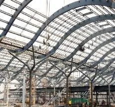
1. Deflection Control Over 75 Meters
A 75-meter column-free span pushes the limits of what a spatial grid can achieve without excessive depth. The governing serviceability criterion is typically deflection: the maximum acceptable downward movement of the roof under design load. For a public building, deflection is typically limited to span/250 for the total load and span/400 for live load — meaning a 75 m span must deflect no more than 300 mm under total load and 187 mm under live load.
Controlling deflection to these limits requires either a sufficiently deep grid (which increases the visual mass of the roof and reduces the clear height below) or pre-cambering (fabricating the grid with an upward curvature that settles to the flat design position under permanent dead load). The design combined both approaches: the grid depth was optimized to provide adequate stiffness, and the grid was pre-cambered to compensate for the dead-load deflection component, leaving only the smaller live-load deflection to be controlled by the grid's inherent stiffness.
2. Dynamic Loads from Passenger Flow and Train Movement
A high-speed rail station is a dynamically loaded environment. The structural floor (which may be a steel-framed mezzanine or a concrete slab on steel framing) experiences dynamic loading from thousands of passengers walking, running, and standing with luggage. While the dynamic component of walking loads is typically small relative to the static weight, it can produce perceptible vibration in long-span floor structures — a comfort issue rather than a safety issue, but one that affects passenger experience and can trigger complaints.
More significantly, the station structure is subject to dynamic loading from passing high-speed trains. A train passing through or beneath a station structure at 250-350 km/h generates pressure waves, ground vibrations transmitted through the track structure, and aerodynamic loading on platform canopy structures. The station's steel structure had to be designed to accommodate these dynamic inputs without resonant amplification — the structural natural frequencies had to be tuned away from the dominant frequencies of the dynamic loading.
3. Architectural Integration and Form
A high-speed rail station is a civic building — its architectural expression contributes to the city's identity and the passenger's experience. The steel structure is not merely a roof support; it is an architectural element visible to every passenger. The grid structure's geometry, member profiles, node design, and surface finish all contribute to the architectural statement.
The challenge was to achieve structural efficiency while meeting architectural requirements for visual rhythm, member slenderness, node elegance, and surface finish quality. The structural engineer's optimal member size (selected for force capacity) may be larger or smaller than the architect's desired member size (selected for visual proportion). The design process required iterative coordination between structural and architectural objectives — a process in which Permanent Steel's in-house engineering team provided the structural analysis that informed the architectural decision-making.
4. Seismic Design for Public Buildings
Xuzhou is located in a moderate seismic zone (design intensity 7, 0.10g). For a public building with high occupancy classification, the seismic performance objectives are elevated: the structure must not only prevent collapse under the rare earthquake but must also maintain operability under the frequent earthquake (the "earthquake that occurs frequently" per GB 50011). This requires that primary structural members remain essentially elastic under the frequent earthquake — no yielding, no permanent deformation — to ensure the station can resume operations immediately after a moderate seismic event.
The long-span grid roof presented specific seismic challenges. The roof's long natural period (1-3 seconds for a 75 m span) creates potential for differential movement between the roof and supporting columns during an earthquake. The roof-column connections had to accommodate this differential movement through specially designed seismic joints — connections that allow controlled sliding and rotation, dissipating seismic energy through friction while protecting the structural integrity of both the roof grid and the columns.
Grid Design, Fabrication, and Erection
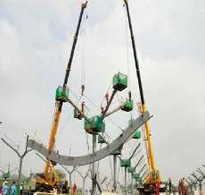
Grid Depth and Module Optimization
The square-pyramid grid was optimized for the 75 m maximum span. The key design parameters — grid depth, module size, and member sizing — were determined through iterative structural analysis:
- Grid depth: Set at approximately 4-5 meters (span/15 to span/18), providing adequate stiffness for deflection control while keeping the roof profile within the architectural envelope
- Module size: Set at approximately 3-4 meters square, balancing member standardization with structural efficiency. Smaller modules increase the number of members and nodes (increasing fabrication and assembly work) while larger modules increase individual member forces (requiring heavier sections). The selected module size optimized the total project cost — steel tonnage plus fabrication labor plus erection labor.
- Member sizing: Members were sized for the governing load combination at each location. Edge members (near the column lines) carry higher forces than interior members, and were correspondingly larger. Mid-span members carry lower forces and were lighter. This variable sizing reduces total steel tonnage by 15-25% compared to a uniform-section alternative.
Bolted-Sphere Node System
The grid connections used our bolted-sphere node system — forged steel spheres with pre-drilled and pre-threaded connection points at the precise angles required by the grid geometry. This system provides several advantages for a project of this scale:
- No field welding of primary connections: All primary structural connections are bolted, reducing field labor, eliminating field weld quality risk, and allowing erection in adverse weather
- Factory precision: Node drilling angles are controlled by CNC machining, ensuring that members meet at the designed angles without field adjustment
- Inspection simplicity: Bolted connections are verified by torque wrench — a faster and more certain inspection method than radiographic or ultrasonic weld testing
- Connection capacity: The bolted sphere connection resists both tension and compression, and the threaded bolt provides a positive mechanical interlock that is not dependent on friction alone
Pre-Camber Fabrication
The grid was fabricated with pre-camber — a built-in upward curvature equal to the predicted dead-load deflection. This pre-camer was achieved by adjusting the member lengths and node positions during fabrication: top chord members were slightly shorter and bottom chord members slightly longer than their nominal lengths, creating a curvature that is built into the structure before it is loaded.
Under dead load, the grid deflects downward until the pre-camber is consumed and the grid sits at the design (flat) position. The residual deflection under live load is then a small fraction of the total deflection that would occur without pre-camber. This technique allows a shallower grid depth (and therefore a lighter steel tonnage) to satisfy the same deflection limit — a structural efficiency that is difficult to achieve without precise fabrication control.
Erection of a 75-Meter Span Grid
Erecting a 75-meter span grid structure is an engineering project in itself. The grid cannot be lifted as a single piece — it is too large and too heavy for any single crane. The erection method involved:
- Sectional assembly: The grid was divided into erection sections, each sized for crane capacity and transport within the station footprint
- Temporary shoring: Temporary support towers were erected at intermediate positions to support the partially completed grid until it achieved self-supporting geometry
- Progressive closure: Sections were installed from the column lines inward, with the grid achieving self-supporting capacity when the final closure section was installed and the grid formed a complete structural system
- Shoring removal: Temporary supports were removed in a controlled sequence, allowing the grid to assume its design deflection profile under self-weight
The advantage of fabricating the grid in our Xuzhou facility — the same city where the station was being built — cannot be overstated. Transport distances were minimal, allowing just-in-time delivery of grid sections. Trial assembly of critical sections in the factory verified geometric compatibility before shipment. And our engineering team was available on-site within hours, not days, to address any erection queries.
Our Flagship, Our Home
The Xuzhou High-Speed Railway Station is, for Permanent Steel, the project that defines our identity. It is the largest, most visible steel structure in our home city — a building that every Xuzhou resident sees, every visitor passes through, and every prospective customer can visit. The 75-meter column-free span, the square-pyramid grid structure, and the bolted-sphere connections are not abstract capabilities described in a brochure; they are physical realities that can be touched, photographed, and verified.
The station serves as a live proving ground for our manufacturing system. Every bolted sphere in the roof grid was machined in our factory. Every member was CNC-cut and drilled to tolerance. Every coating was applied under controlled conditions. And all of these elements are visible, assembled, and performing — not in a test yard, but in a building that processes millions of passengers per year.
For Xuzhou, the station reinforces the city's position as a national transportation hub. The high-speed rail network connects Xuzhou to Beijing in approximately 3 hours, to Shanghai in approximately 2.5 hours, and to dozens of intermediate cities — making Xuzhou a practical destination for customers who wish to visit our factory and inspect our quality in person, while also connecting the city to the national economy at rail speeds.
For the steel structure industry, this project demonstrates that Chinese fabricators can deliver 75-meter span spatial grid structures with the precision, quality, and architectural finish required for major public infrastructure. The combination of bolted-sphere technology, CNC-driven fabrication, pre-camber engineering, and sequential erection methodology represents a capability profile that few fabricators worldwide can match — and one that is on permanent display in the heart of our home city.
Systems Used in This Project
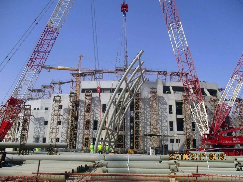 Structure
Square-Pyramid Grid
Orthogonal square-on-square offset spatial grid with alternating upward and downward pyramids. Efficient 75m column-free span with architectural expression.
 Components
Steel Structure Components
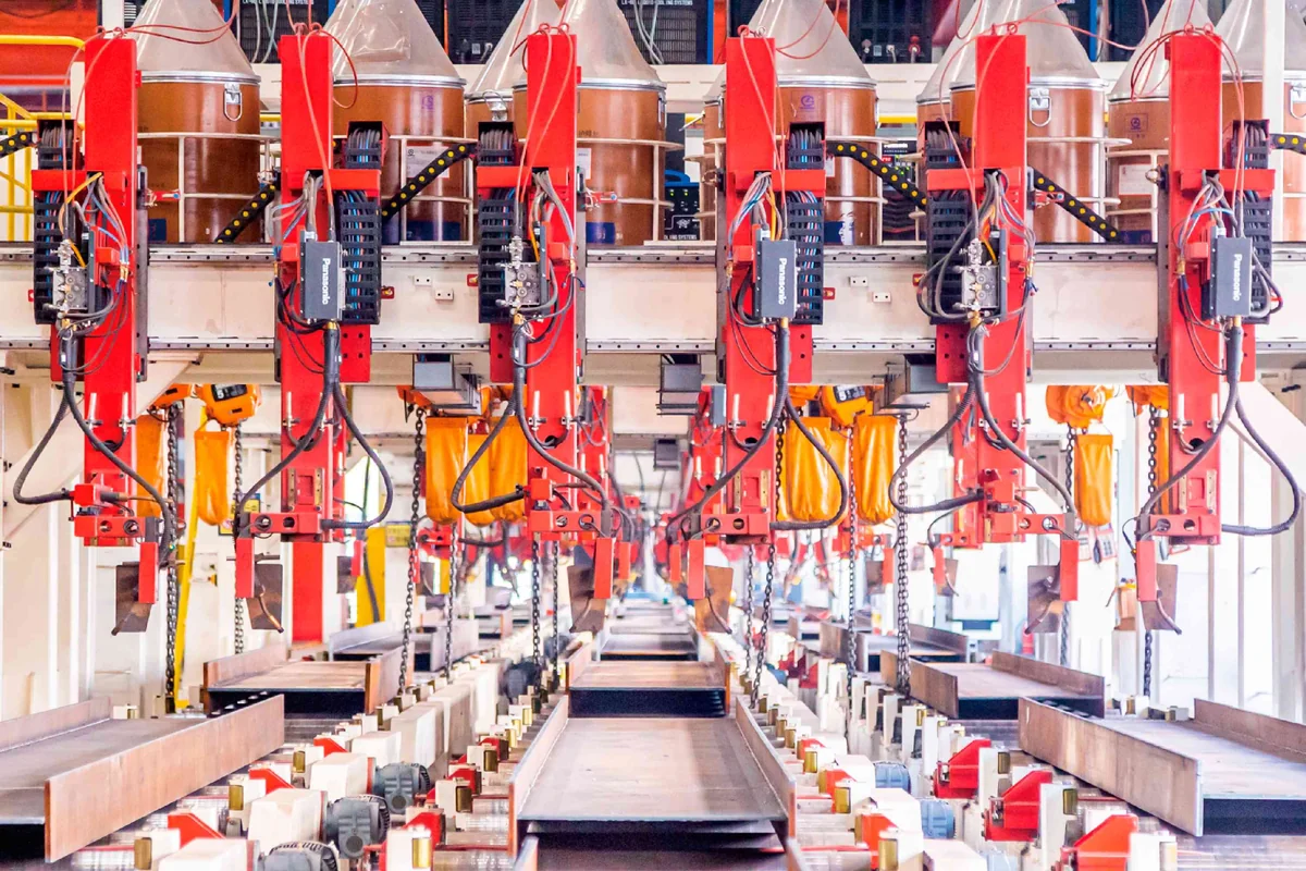
CNC-fabricated members, bolted sphere nodes, and connection hardware. Pre-camber built into member lengths for deflection control.
 Envelope
Metal Roof Envelope
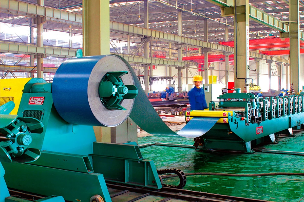
Standing seam metal roofing with integrated insulation and daylighting. Weatherproof, thermally efficient, integrated with the grid structure depth.
Need a Column-Free Span?
Our spatial grid structures achieve spans from 30 to 100+ meters with factory-prefabricated, field-bolted assembly. Visit our Xuzhou factory and see the high-speed rail station roof in person. Contact our engineering team to discuss your project.
Request a Consultation WhatsApp Our Engineer