
Synchronized Jacking Installation Over Active High-Speed Rail Tracks
The engineering challenge of installing 75m-span grid roofs without interrupting train operations. Modular ground assembly, synchronized hydraulic lift, thermal expansion across a 70°C annual range, and vibration isolation from trains passing at 350 km/h beneath the structure.
Why Installing a Station Roof Over Live Tracks Changes Everything
A high-speed railway station roof is not just a large-span structure. It is a large-span structure that must be installed while trains continue to run beneath it. This single constraint transforms every aspect of the engineering, fabrication, and installation methodology.
On a conventional construction site, the grid roof is assembled in the air: temporary shoring towers are erected on the ground, grid sections are hoisted by crane and bolted together at elevation, and the shoring is removed after the grid achieves self-supporting geometry. This method is impossible over active tracks. Shoring towers cannot be placed on the track bed. Cranes cannot swing loads over live overhead catenary lines. And the railway operator will not suspend service for the weeks or months that conventional aerial assembly requires.
The solution is synchronized jacking installation: the grid roof is fully assembled on the ground adjacent to the tracks, then lifted as a complete unit — or in large pre-assembled sections — into its final position using a system of synchronized hydraulic jacks. The lift may take hours rather than weeks. During the lift, the structure is supported at multiple points by hydraulic cylinders that are computer-controlled to maintain uniform vertical displacement within a tolerance of ±5mm. Any differential settlement beyond this tolerance triggers automatic correction, preventing the generation of unbalanced internal forces that could damage the grid during the lift.
This is not a standard technique. It requires engineering analysis of the structure's behavior during the lift — a temporary load case that many fabricators never consider. The grid must be designed not only for its permanent support conditions (resting on perimeter columns) but also for its temporary support conditions (resting on jack points that may be in different positions). Member forces during the lift can exceed permanent forces, requiring temporary reinforcement or modified lift point locations. The jacking system must be sized for the full weight of the grid plus cladding plus wind loads during the lift period.
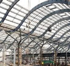
The Engineering of HSR Station Roofs
75m span grid roofs, thermal movement across extreme temperature ranges, and vibration isolation from high-speed train passages.
China's high-speed rail network operates at speeds up to 350 km/h. A station on this network is not merely a building — it is infrastructure that must coexist with a dynamic system generating aerodynamic pressure pulses, ground vibration, and electromagnetic interference. The steel roof structure above the platform tracks must address engineering challenges that no other building type encounters in the same combination.
Clear Span Requirements for Platform Coverage
A high-speed rail station platform typically serves 2-6 tracks, with platform widths of 10-15m per track group. The roof must cover the full platform width without interior columns — columns would obstruct passenger movement, interfere with platform-edge doors, and create safety hazards near the track edge. For a 4-track station with island platforms, the required clear span is typically 60-75m. For larger stations with 6+ tracks, the span may reach 90-100m.
A bolted sphere grid structure achieves these spans with a structural depth of 4-6m (depth-to-span ratio of 1:12 to 1:15). The grid distributes roof load to perimeter supports — typically the station building columns on the concourse side and freestanding columns on the platform edge — without intermediate supports over the tracks. The bolted sphere system is preferred over welded connections for station roofs because field welding over active tracks introduces fire hazards to the overhead catenary system and requires hot-work permits that further constrain the construction window.
Thermal Expansion Across a 70°C Annual Range
Many high-speed rail stations in China are located in regions with extreme continental climates. Stations in the northeast (Harbin, Changchun) experience winter temperatures of -30°C; stations in the northwest (Urumqi, Lanzhou) experience summer surface temperatures of 50°C on dark metal roofing. The annual temperature range for the steel roof structure can reach 70-80°C.
Steel has a coefficient of thermal expansion of 12×10⁻⁶ per °C. For a 75m span grid roof experiencing a 70°C temperature change, the theoretical thermal movement at the free end is:
ΔL = α × L × ΔT = 12×10⁻⁶ × 75,000mm × 70°C = 63mm
A 63mm movement is not a theoretical concern — it is a real displacement that must be accommodated by the support connections. If both ends of the grid are fixed, this thermal movement generates an axial force of approximately 1,900 kN in the grid chord — enough to crack supporting columns or fracture connections. The solution is to design one end of the grid as fixed (resisting horizontal forces from wind and seismic) and the other end as sliding, using elongated slotted bolt holes or PTFE-coated sliding bearings that allow the grid to expand and contract freely.
For longer station roofs (100m+ along the track axis), the thermal movement along the track axis must also be accommodated. Expansion joints divide the roof into segments of 40-60m, each segment thermally independent. The grid at each expansion joint is supported on a double-column line, with each segment sliding independently on its own bearings.
Vibration Isolation from High-Speed Train Passages
When a high-speed train passes through a station at 350 km/h, it generates an aerodynamic pressure pulse — a compression wave followed by a rarefaction wave — that impinges on the platform roof. This pulse has a magnitude of approximately 500-1000 Pa (equivalent to 0.05-0.10 kN/m²) and a duration of 0.5-1.5 seconds. The pulse applies a transient upward and then downward force to the roof structure.
While the magnitude of this force is small compared to the roof's dead load, its dynamic nature is the concern. If the roof's natural frequency is close to the pulse frequency, resonance amplification can multiply the response by a factor of 2-4. A 1000 Pa pulse amplified 4 times becomes 4000 Pa — no longer negligible, especially when combined with wind uplift.
More significantly, ground-borne vibration from train passages propagates through the platform structure and into the roof supporting columns. This vibration, typically in the 5-30 Hz range, can couple with the roof's higher-order vibration modes. The result is perceptible ceiling oscillation that can dislodge ceiling panels, rattle light fixtures, and create an unsettling experience for waiting passengers.
We address train-induced vibration through:
- Natural frequency verification: The grid's fundamental frequency is calculated in the structural model and verified to be above 3 Hz (well clear of the 1-2 Hz excitation band of pressure pulses and the 5-30 Hz band of ground vibration)
- Vibration isolation bearings: Elastomeric or sliding bearings at the column-roof interface decouple the roof from ground-borne vibration, reducing transmitted vibration by 60-80% in the 5-30 Hz range
- Non-structural element anchorage: Ceiling systems, light fixtures, and signage are anchored to resist the acceleration levels predicted at their attachment points, preventing rattling and dislodgement
- Aerodynamic profiling: For stations where trains pass at full speed without stopping, the roof's leading edge is aerodynamically profiled to reduce the magnitude of the pressure pulse impinging on the roof surface
Wind Management and Structural Monitoring During the Lift
A grid roof assembled on the ground and lifted into position by synchronized jacks is, during the lift, a structure in an unstable support configuration. Unlike its permanent condition — where the grid rests on continuous perimeter bearings — during the lift the grid is supported at discrete jack points that may be 20-30m apart. The structural analysis for this temporary condition is as critical as the analysis for the permanent condition.
Wind is the governing load during the lift. A 75m × 120m grid roof assembled on the ground presents a sail area of 9,000 m² — even a moderate 6 m/s wind generates 20-30 kN of horizontal force on the assembled structure. This force creates lateral displacement at the jack points, generating bending moments in grid members that were designed for vertical gravity load, not horizontal wind load. The lift is scheduled for a window when wind speed is forecast below the pre-calculated safe limit, typically 6-8 m/s for a grid of this size.
During the lift, real-time monitoring provides three layers of safety verification. First, displacement sensors at each jack point track vertical position to ±1mm resolution, with automatic synchronization correction if any jack deviates beyond tolerance. Second, tilt sensors at the grid's perimeter detect any rotation of the structure during the lift — rotation indicates uneven loading, which could signal wind force distribution that the synchronization system cannot correct. Third, strain gauges on critical members monitor stress levels during the lift, comparing actual values against the structural model's predicted values for the temporary support condition. Any strain exceeding 80% of predicted capacity triggers an immediate halt for engineering review.
After the grid reaches its permanent position and is connected to the support bearings, the monitoring system transitions from lift control to structural health monitoring. The strain gauges remain in place for the first 12 months of operation, recording the structure's response to thermal cycles, train passages, and wind events. This data verifies that the as-built structure performs as the as-designed model predicted — the ultimate confirmation that the engineering was correct.
Synchronized Jacking: How a 75m Roof Goes Up Without Stopping Trains
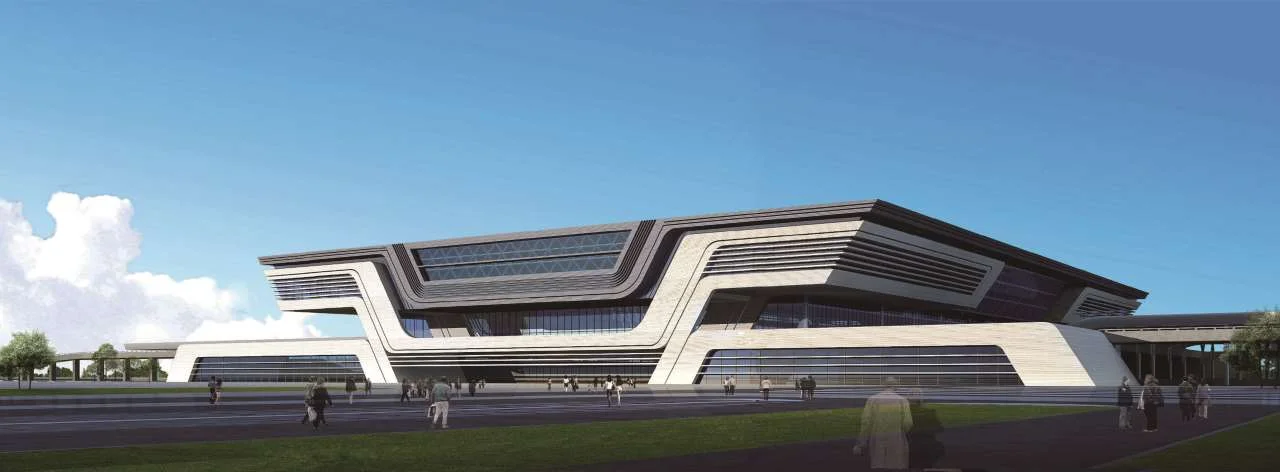
Stage 1: Ground Assembly
The grid roof is assembled at ground level on a flat assembly area adjacent to the tracks. This area must be large enough to accommodate the full grid footprint (75m × station length) and must support the combined weight of the grid plus jacking equipment. Bolted sphere nodes, steel tubes, and sealing plates are assembled according to the 3D model node ID system. Connections are bolted and torque-verified on the ground, where access is easy and quality control is straightforward — no workers at 20m elevation, no weather constraints on bolting operations, no crane time consumed by connection work.
Stage 2: Jack Placement and Synchronization Setup
Hydraulic jacks are placed at the lift points determined by the structural analysis. These points are selected to minimize member forces during the lift — they may coincide with permanent support points or may be at different locations where temporary support is more efficient. The jacks are connected to a computerized synchronization system that monitors displacement at each jack to ±1mm resolution. The system is programmed with the target lift height and the acceptable differential settlement tolerance (typically ±5mm between adjacent jacks). If any jack deviates beyond tolerance, the system automatically pauses and corrects before continuing.
Stage 3: The Lift
The lift is performed during a pre-arranged track possession window — typically a 2-4 hour overnight maintenance block when train service is reduced or suspended. The grid is lifted at 0.5-1.0 m/min, reaching its final elevation of 15-25m above platform level in 30-60 minutes. During the lift, wind monitoring is continuous; if wind speed exceeds the pre-calculated safe limit (typically 8-10 m/s for a partially supported grid), the lift is halted and the structure is secured at its current elevation until conditions improve.
Stage 4: Permanent Connection
Once the grid reaches final elevation, it is translated horizontally (if required for final positioning) and lowered onto permanent support bearings. The permanent connections are completed — bolted or welded depending on the connection design — and the jacking system is removed. The entire process from ground assembly to permanent connection may span several weeks of preparation, but the critical lift itself occupies only hours, and track interruption is minimized or eliminated entirely.
Railway Station Projects We Have Delivered
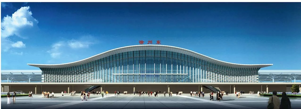 HSR Hub
Xuzhou East High-Speed Rail Station
A major HSR hub on the Beijing-Shanghai line. Large-span grid roof covering multiple platform tracks, engineered for thermal movement across a 65°C annual range and vibration isolation from 350 km/h train passages.
Northeast China
Daqing West Station
Railway station in a region with extreme winter temperatures reaching -30°C. Steel grid roof designed for a 75°C annual thermal range, with sliding bearings and expansion joints accommodating seasonal movement.
Planning a Railway Station Steel Roof?
Send us your platform layout, track configuration, required clear span, and climate data. Our engineering team will respond within 24 hours with a feasibility assessment, installation methodology, and budget quotation — including synchronized jacking feasibility over active tracks.
Email: market@permanentsteelstructure.com | WhatsApp: +86 18621689980 | Phone: +86 516-83269982