
Modular Building Construction: Antarctic Research Station Case Study
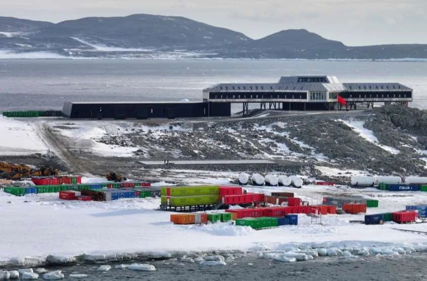
Modular building construction is often marketed as a speed and cost optimization — "build faster, build cheaper." But the most compelling case for modular construction is not about cost or schedule. It is about constructing where construction is otherwise impossible. The Antarctic Ross Sea Station (Qinling Station) is such a case.
In Antarctica, there is no concrete supply, no welding gas delivery, no equipment rental, no spare parts depot, and no rescue service. The construction window is approximately 60 days during the austral summer (November to January), when temperatures rise to a balmy −10 to −20°C and the sea ice recedes enough for a supply ship to reach the site. During the remaining 305 days, the station must survive without any human intervention, enduring temperatures below −40°C, katabatic winds exceeding 200 km/h, and total darkness.
This is not a marketing case study about the benefits of modular construction. It is a specific engineering account of how modular building technology solved problems that no other construction method could solve. Every design decision discussed here was driven by a real constraint of the Antarctic environment, not by a preference for modularity.
1. Why Modular? The Constraints That Eliminated Alternatives
To understand why modular construction was the only viable approach for the Antarctic station, consider the alternatives and why each was eliminated:
Alternative 1: Conventional Stick-Built Construction
Steel members are shipped to site and assembled with field welding. Eliminated because field welding at −20°C with 200 km/h winds is impractical — even with heated enclosures, the wind chill, gas shielding disruption, and hydrogen cracking risk make reliable welding impossible. Additionally, the 60-day construction window does not allow time for site fabrication, inspection, and coating repair.
Alternative 2: Precast Concrete
Concrete structures are cast off-site and shipped as panels. Eliminated because concrete cannot be poured in Antarctica (the water would freeze before hydration), and shipping precast concrete panels (which are heavy and bulky) is logistically prohibitive. The weight-to-strength ratio of concrete is 3-5 times worse than steel, meaning a concrete structure would require 3-5 times more shipping capacity.
Alternative 3: Aluminium Space Frame
Aluminium is lighter than steel and does not corrode. Eliminated because aluminium's coefficient of thermal expansion (23 × 10-6/°C) is nearly double that of steel (12 × 10-6/°C), meaning thermal movement over the temperature range would be twice as large. Aluminium's lower modulus of elasticity (70 GPa vs 206 GPa for steel) means the structure would be 3 times more flexible, which is unacceptable under 200 km/h wind loads. Finally, aluminium welding at field scale in Antarctica faces the same environmental challenges as steel welding.
The Modular Solution
Modular construction with bolted steel connections solved every constraint: all welding was completed in our Xuzhou factory under controlled conditions; modules were sized to fit shipping containers; the entire structure was designed for bolted assembly with no field welding; and the assembly sequence was rehearsed through digital pre-assembly to guarantee fit-up on the first attempt.
2. Module Design: Shipping Container Constraints
The logistics chain from Xuzhou, China to the Antarctic coast involves truck transport to a port, ocean shipping across the Pacific and Southern Ocean, transfer to an icebreaker, and finally cargo handling on the sea ice at the destination. Every module had to fit within the dimensional constraints of a standard 40-foot shipping container:
- Maximum external length: 12.03 m (40 ft container)
- Maximum external width: 2.44 m
- Maximum external height: 2.90 m (high-cube container)
- Maximum payload weight: 26,000 kg per container
These constraints directly governed the structural design. The primary steel frame modules were designed at 11.5 m × 3.0 m × 2.8 m (length × width × height), fitting within a high-cube 40-foot container with 100 mm clearance on each side for packaging and handling. Each module weighed approximately 8,500 kg (steel frame + insulation + cladding), well within the container payload.
Module-to-Structure Relationship
The station's architectural form — an elevated, linear building oriented to minimize wind exposure — was derived from the module dimensions. The station is composed of 12 primary structural modules, each 11.5 m long, connected end-to-end to create a 138 m total length. The width is 2 modules (6.0 m), and the height is 2 modules stacked (5.6 m), creating a total enclosed area of approximately 1,600 m2 across two levels.
This is an important point: the modular approach did not compromise the architecture — it defined it. The station's form is a direct expression of the shipping container constraint, the Antarctic wind environment, and the elevated platform requirement. The result is a building that is simultaneously optimized for logistics, structure, and environment.
3. Connection Systems: Bolted, No Field Welding
The defining engineering decision was the connection system. Every connection in the field assembly — module-to-module, module-to-foundation, and secondary member-to-module — uses high-strength bolted connections. No field welding. This decision cascaded into every other design choice.
Module-to-Module Connection
Adjacent modules are connected at four points: two at the top chord and two at the bottom chord of the frame. Each connection uses four M24 10.9-grade bolts in a slip-critical configuration, with sandblasted faying surfaces (slip coefficient μ = 0.45). The connection is designed for:
- Axial force: 180 kN (from dead load and snow load transferred through the frame)
- Shear force: 420 kN (from wind load perpendicular to the building length)
- Uplift force: 95 kN (from wind uplift on the roof and the cantilevered platform)
The slip-critical connection provides the stiffness needed to make the modular building behave as a continuous structure, not as separate boxes. The bolt pretension (245 kN per M24 10.9 bolt, verified by the turn-of-nut method) ensures that the connection does not slip under service loads, and only slips (yielding) under the extreme overstrength forces of a design-level windstorm — the ductile behaviour we want.
Why Not Welded Connections?
Welded module-to-module connections would provide a stiffer, more monolithic structure. But they were eliminated for three engineering reasons:
- Welding quality at −20°C: Even with preheat (80-120°C) and heated enclosures, the risk of hydrogen-induced cracking in Q355D steel at low ambient temperature is non-trivial. A cracked weld in Antarctica cannot be excavated and re-welded — the structure must be right the first time.
- Coating integrity: Field welding destroys the shop-applied C5-M coating system (see our ISO 12944 guide). Repairing the coating in the field — abrasive blasting, primer, three epoxy coats, polyurethane topcoat — is impossible in Antarctica. A bolted connection preserves the coating entirely.
- Disassembly: The station has a design life of 25-50 years, but Antarctic environmental protocols require complete removal of all structures at end-of-life. Bolted connections allow the station to be disassembled and removed; welded connections would require cutting, which is both difficult and environmentally undesirable.
4. Wind Load Engineering: 200 km/h Katabatic Winds
Antarctica is the windiest continent on Earth. Katabatic winds — gravity-driven flows of cold, dense air descending from the polar plateau — can reach sustained velocities exceeding 200 km/h (55 m/s) at coastal stations. The wind load on the station is the governing structural design case, exceeding snow load, dead load, and live load by a significant margin.
Wind Pressure Calculation
The basic wind pressure at 55 m/s is:
w0 = 0.5 × ρ × v2 = 0.5 × 1.29 kg/m3 × (55)2 = 1,950 Pa = 1.95 kN/m2
For a building with an aerodynamic shape factor (Cp) of +0.8 on the windward face and −0.5 on the leeward face, the total pressure differential is 1.3 × 1.95 = 2.54 kN/m2. However, this basic calculation significantly underestimates the actual load because:
- Katabatic wind characteristics: Katabatic winds are not gusty like tropical cyclones — they are sustained, directional flows that can last for days. The structure must resist the full wind pressure for the duration, with no reduction from gust factors.
- Density at altitude: The cold, dense Antarctic air (−40°C) is approximately 15% denser than standard air (1.29 vs 1.12 kg/m3), increasing the wind pressure by 15%.
- Aerodynamic amplification: The station's elevated platform creates a venturi effect underneath, accelerating the wind beneath the structure and increasing the uplift on the floor.
Accounting for these factors, the design wind pressure was 3.5 kN/m2 on the windward face and 2.1 kN/m2 uplift on the roof — forces that govern the design of every primary member, connection, and foundation.
Aerodynamic Form Optimization
The station's architectural form was aerodynamically optimized using CFD (Computational Fluid Dynamics) analysis to minimize wind loading. Key form decisions driven by the wind analysis:
- Orientation: The long axis of the building is aligned with the prevailing katabatic wind direction, minimizing the windward face area. The windward face is only 6.0 m × 5.6 m = 33.6 m2, compared to 138 m × 5.6 m = 773 m2 if the building were oriented perpendicular to the wind.
- Tapered leading edge: The windward end of the building is tapered to reduce flow separation and the associated pressure spike. This reduces the shape factor from +0.8 (flat face) to approximately +0.6.
- Rounded roof: The roof is slightly curved (radius = building width) to reduce the separation zone on the leeward roof, which reduces the negative pressure (uplift) from −0.5 to approximately −0.4.
- Elevated platform: The building is raised on steel legs 2.0 m above grade, allowing katabatic wind to pass beneath the structure rather than accumulating against it. This prevents snow accumulation against the building face — a phenomenon that buried earlier Antarctic stations.
5. Insulation Integration: Structural and Thermal Design
The Antarctic station must maintain an interior temperature of +18°C while the exterior is at −40°C — a 58°C temperature differential. The thermal performance of the building envelope is a structural concern, not just an energy concern, because of thermal bridging through the steel frame.
Thermal Bridge Analysis
Steel has a thermal conductivity of 50 W/(m·K), approximately 1,500 times that of insulation (0.034 W/(m·K)). If the steel frame directly connects the interior and exterior surfaces, it creates a thermal bridge that transfers heat from inside to outside at a rate of 50/0.034 = 1,470 times the rate through the insulation. This causes:
- Excessive heat loss (increasing energy consumption by 30-50%)
- Condensation on the interior surface of the steel (causing mould, corrosion, and ice formation)
- Differential thermal movement between the bridged and non-bridged areas (causing coating stress and structural deformation)
Structural Thermal Break
We resolved the thermal bridge by designing a structural thermal break at the connection between the steel frame and the building envelope. The thermal break consists of a 50 mm thick fibre-reinforced polyamide plate that is strong enough to transfer the connection forces (shear and uplift) but has a thermal conductivity of only 0.30 W/(m·K) — reducing the thermal bridge by a factor of 167.
The polyamide plate is bolted between the steel frame and the cladding bracket, using the same M24 bolted connection that joins the modules. The plate's compressive strength (120 MPa) exceeds the bearing stress at the connection (65 MPa), and its shear strength (75 MPa) exceeds the connection shear demand (42 MPa). The thermal break adds 4 kg per connection — negligible compared to the 8,500 kg module weight.
Insulation System
The building envelope uses 300 mm of PIR (polyisocyanurate) insulation, providing a thermal resistance of R = 8.8 m2·K/W. The overall U-value of the envelope, including the thermal break, is 0.11 W/(m2·K). At the 58°C temperature differential, the heat loss through the envelope is:
Q = U × A × ΔT = 0.11 × 1,600 m2 × 58 = 10,208 W = 10.2 kW
This is the steady-state heat loss. The heating system is sized for 25 kW (providing a 2.4x safety factor for wind infiltration, door opening, and extreme cold events). The insulation is integrated into the module during factory fabrication — it is not a separate layer applied on site. This ensures consistent insulation quality with no gaps or compression that would degrade thermal performance.
6. Raised Platform: Snow Accumulation Engineering
Antarctic stations face a unique threat that no temperate building encounters: snow burial. Katabatic winds transport enormous quantities of snow, which accumulates against any obstacle. Early Antarctic stations (built at grade) were buried within 5-10 years, requiring expensive snow excavation or abandonment.
Snow Accumulation Modelling
We modelled snow accumulation around the station using CFD with particle tracking. The model predicted snow drift patterns for the prevailing wind direction over a 25-year period. The key findings were:
- At grade: Snow accumulates against the windward face at a rate of 2-3 m per year, reaching the eave height (5.6 m) within 2-3 years and burying the building within 5 years.
- At 2.0 m elevation: The building acts as a porous barrier, with wind accelerated beneath it. Snow passes through beneath the building rather than accumulating against it. The model predicts less than 0.5 m of accumulation over 25 years.
Based on this analysis, the building is elevated on steel legs at 2.0 m above grade. The legs are designed for the wind load transferred from the building above (260 kN per leg, including the uplift case) and for the snow load that accumulates on the ground beneath (modelled as a 1.0 m snow depth at 400 kg/m3 density, providing 2.0 kN/m2 lateral pressure on the lower 1.0 m of the legs).
Fatigue Design for the Platform Legs
The platform legs are subjected to cyclic wind loading from katabatic events (estimated 50 significant wind events per year, each lasting 12-48 hours). Over a 25-year design life, this is 1,250 major cycles. The leg-to-foundation connection and the leg-to-module connection are designed for a stress range of 80 MPa (the difference between peak wind stress and dead-load stress), which is well within the fatigue limit for Q355 steel with Category C detailing (per GB 50017 fatigue design).
7. Construction Sequence: 60-Day Window
The construction sequence was planned to the day, with contingency built into each phase:
- Days 1-7: Ship unloading and module staging. The icebreaker creates a channel to the shore; cargo is transferred by sled to the building site, 200 m inland.
- Days 8-15: Foundation installation. Pre-drilled rock anchors (M30, 1.5 m embedment in bedrock) are installed at each leg location. The rock anchors provide tension capacity for wind uplift and are the only concrete-free foundation solution available.
- Days 16-35: Module erection. Modules are lifted by crane (a tracked crane shipped specifically for this purpose) and bolted to the foundation anchors and to adjacent modules. Target: 1 module per 1.5 days, allowing 4 days of weather contingency.
- Days 36-45: Envelope completion. Cladding panels, insulation, windows, and doors are installed between the structural modules. All connections are bolted.
- Days 46-55: Mechanical, electrical, and plumbing systems commissioning. Interior fit-out.
- Days 56-60: Final inspection, bolt torque verification, coating touch-up, and station handover.
Each phase had a defined contingency: weather days (when wind exceeds crane operating limits), equipment failure, and supply chain delays. The total contingency was 12 days — 20% of the construction window — which was consumed almost entirely by weather delays during the actual construction.
Digital Pre-Assembly: Guaranteeing Fit-Up
Because there is no opportunity for field modification (no cutting, welding, or re-drilling in Antarctica), every module must fit perfectly on the first attempt. We used digital pre-assembly — a 3D model of the entire structure with every module, every bolt hole, and every connection detail modelled to ±1 mm tolerance. The model was checked for interferences (overlapping members, misaligned bolt holes, cladding conflicts) before fabrication began. During fabrication, each module was surveyed with a laser tracker to verify that its as-built dimensions matched the model within ±2 mm. Any module exceeding this tolerance was reworked in the factory — not on site.
8. Lessons for Non-Antarctic Modular Projects
While the Antarctic project represents an extreme case, the engineering principles translate directly to less extreme modular building projects:
- Module sizing is driven by logistics, not by architectural preference. For most projects, the shipping constraint (container dimensions or truck dimensions) defines the module size. Design with the logistics in mind from the start.
- Bolted connections enable disassembly and relocation. For temporary structures, disaster-relief housing, and facilities with a defined service life, bolted connections provide a path to recovery and reuse that welded connections do not.
- Factory-controlled welding quality exceeds field welding quality, always. If your project involves critical welds, perform them in the factory, not on site.
- Digital pre-assembly eliminates fit-up problems. The cost of 3D modelling and laser-tracker verification is a fraction of the cost of field modifications.
- Thermal bridging is a structural issue, not just an energy issue. If your steel frame connects interior and exterior environments, design a structural thermal break.
For more on our modular building technology system, visit our modular integrated building product page. For the full project details, see the Antarctic Ross Sea Station project page.
Conclusion
Modular construction in Antarctica was not a choice — it was the only engineering solution that satisfied every constraint: impossible logistics, extreme cold, extreme wind, no field welding, no maintenance access, and a 60-day window. The design decisions — module sizing from shipping constraints, bolted connections for coating and disassembly, raised platform for snow management, structural thermal breaks for insulation continuity — were all direct responses to specific environmental demands.
This is the essence of engineering: not applying a preferred solution, but finding the solution that the constraints demand. If your project faces constraints that conventional construction cannot meet — remote location, extreme environment, compressed schedule, or disassembly requirement — contact our engineering team. We have solved these problems before, and we can solve them again.
Need Expert Engineering for Your Steel Structure Project?
Our engineers bring 25+ years of experience in modular steel structure design, including the extreme engineering of the Antarctic Ross Sea Station. Whether your project is in Antarctica or an industrial park, we can engineer modular solutions that meet your constraints. Send us your project requirements today.
Request a Consultation