
Shop-Fabricated Segments for Bridge Lifecycle Performance
Steel bridges replace concrete for 50-200m spans because they are lighter, faster to install, and easier to inspect. The key is shop fabrication: every truss segment is manufactured, trial-assembled, and quality-verified in the factory, then transported to site for bolted field connections. We have built the 748 m covered bridge — a building-bridge hybrid — and delivered bridge projects across Pakistan and Indonesia.
Why Steel Bridges Replace Concrete for 50-200m Spans — and Why Prefabrication Is the Key
For bridge spans of 50-200m, steel is not merely an alternative to concrete — it is a fundamentally different approach to the bridge lifecycle. A concrete bridge of this span range is cast in place or segmentally precast, requiring extended on-site formwork, curing time, and traffic management. A steel bridge is fabricated in the shop, transported in segments, and bolted together on site in days rather than weeks.
The shop fabrication advantage is not just about speed. It is about quality control. In a fabrication shop, welding is performed under controlled temperature, humidity, and wind conditions by certified welders using procedures qualified to the applicable code (AWS D1.5 for highway bridges, AASHTO for US projects, GB 50205 for Chinese projects). Every weld is inspected — visually, by magnetic particle testing for surface indications, and by ultrasonic testing for internal soundness. The inspection happens in the shop, where access is easy and rework is inexpensive, not on a bridge 30m above a river where access requires scaffolding and rework closes the bridge.
The transport logistics of steel bridge segments is a design constraint that must be addressed at the engineering stage, not after fabrication. A truss segment 3.5m wide, 4m deep, and 20m long weighs 15-25 tonnes and can be transported by standard flatbed truck on most highways. A segment wider than 4m requires special permits; wider than 5m requires escort vehicles and route surveys; longer than 25m requires special routing to avoid tight turns. Our engineering team designs the segment breaks at locations that optimize both structural efficiency (breaks at zero-moment points where possible) and transport logistics (segments within standard permit limits).
For our steel structure bridge projects, we hold the Class-1 Building Construction General Contracting qualification and the Class-1 Steel Structure Specialized Contracting qualification — the highest tiers for bridge construction in China's system. This authorizes us to design, fabricate, and install bridges of any span and any structural classification, from pedestrian walkways to highway loadings.

Fatigue Design, Seismic Isolation, and the Building-Bridge Hybrid
The engineering systems that distinguish steel bridge design from building design — and why the 748 m covered bridge defies conventional categorization.
Fatigue Design for Traffic Loads
A bridge is a dynamically loaded structure. Every vehicle that crosses it applies a moving point load that cycles through the structure's members and connections. Over a 50-100 year design life, a highway bridge may experience 50-200 million truck load cycles — a fatigue loading regime that no building structure encounters.
Fatigue design for steel bridges is governed by the stress range at fatigue-critical details and the number of cycles. The critical details are not the primary members themselves — a well-designed chord or diagonal is sized for strength, and its fatigue life is usually adequate. The critical details are the connections: the welds attaching gusset plates to chords, the welds connecting transverse stiffeners to webs, the bolt groups at field splices, and the welds at bearing stiffeners. These are the locations where stress concentrations amplify the nominal stress range, and where fatigue cracks initiate.
Our fatigue design approach for steel structure bridges follows:
- Detail classification: Every welded and bolted detail is classified per the fatigue category tables in the applicable code (AASHTO LRFD Table 6.6.1.5.3-1, Eurocode 3 Table 8.1-N, or GB 50017). The category determines the allowable stress range for a given cycle count.
- Stress range calculation: For each fatigue-critical detail, the stress range is calculated from the structural analysis under the fatigue truck loading (a design truck with specified axle spacing and weight, applied at multiple positions to maximize the stress range at the detail).
- Miner's rule cumulative damage: The fatigue damage from trucks of varying weights is accumulated using Miner's rule, which sums the damage ratio (actual cycles / allowable cycles) across all truck weight categories. The cumulative damage must be less than 1.0 at the design life.
- Detail improvement: Where a detail's fatigue capacity is insufficient, the detail is re-engineered: welds are reoriented to reduce stress concentration, grinding of weld toes reduces the stress concentration factor, or bolted splices replace welded splices at high-stress-range locations.
Seismic Isolation Bearings
In seismic zones, the bridge's superstructure (the steel truss or girder) must be isolated from the substructure (the piers and abutments) to prevent the transfer of damaging seismic forces. The isolation is achieved through seismic isolation bearings — devices placed between the superstructure and the substructure that decouple the horizontal motion of the ground from the horizontal motion of the bridge deck.
We engineer three types of seismic isolation bearings, selected based on the bridge's seismic hazard, span, and functional requirements:
- Elastomeric bearings: Layers of rubber interleaved with steel shim plates. The rubber provides horizontal flexibility (allowing the bridge to move relative to the piers), while the steel plates provide vertical stiffness (supporting the bridge's dead and live loads). Suitable for low to moderate seismic zones.
- Lead-rubber bearings (LRB): A lead core is inserted into an elastomeric bearing. The lead core yields under seismic displacement, dissipating energy through hysteretic damping. Suitable for moderate to high seismic zones. The LRB reduces the seismic force transferred to the substructure by 40-60% compared to a non-isolated bridge.
- Friction pendulum bearings (FPB): A sliding bearing with a curved concave surface. The bridge deck slides on the curved surface during an earthquake, with the curvature providing a restoring force that returns the bridge to its centered position. The friction between the sliding surfaces provides energy dissipation. Suitable for high seismic zones and long-span bridges where large displacement capacity is required.
The bearing design is not just a device specification — it is integrated into the structural analysis. The bearings' stiffness and damping properties are modeled in the bridge's seismic analysis, and the reduced seismic forces in the superstructure and substructure are used to optimize member sizes. A bridge with seismic isolation bearings has lighter superstructure members and smaller substructure elements than a non-isolated bridge of the same span — the isolation system pays for itself through structural savings.
The 748 m Covered Bridge: A Building-Bridge Hybrid
Our 748 m covered bridge project represents a structural type that defies conventional categorization. It is a bridge — it carries pedestrians across a river or valley — but it is also a building, with a roof, walls, and enclosed interior space. The structure must resist not only bridge loads (traffic, wind on the deck) but also building loads (wind on the walls and roof, snow on the roof, seismic mass of the envelope).
The engineering challenge of a covered bridge is the interaction between the bridge structure and the building envelope. The bridge trusses carry the deck load and resist the horizontal forces from the envelope. The envelope — roof, walls, end gables — adds wind area that the bridge trusses were not designed for in an open-deck configuration. The truss top chord, which in a conventional bridge is a compression member carrying deck load, becomes a combined compression-bending member carrying both deck load and wind load from the wall above.
The 748 m length of the bridge means thermal expansion is a major design consideration. A 748 m steel bridge experiencing a 60°C temperature change expands by approximately 540 mm at the free end — accommodated by expansion joints at each span break. The covered envelope, however, moderates the temperature range: the enclosed interior experiences less temperature variation than an exposed bridge, reducing the thermal movement demand. This is one of the structural benefits of the covered bridge typology — the envelope that adds wind load also reduces thermal stress.
For the covered bridge, we deployed a modular truss system: the bridge is divided into structural modules of 40-60m, each module shop-fabricated, transported, and bolted together at site. The modular breaks coincide with expansion joint locations, so each module is thermally independent. The bolted field splices are designed as pinned connections (transferring shear but not moment), allowing each module to articulate independently under thermal movement and differential settlement.
From Shop to Site: How a Steel Bridge Goes Up
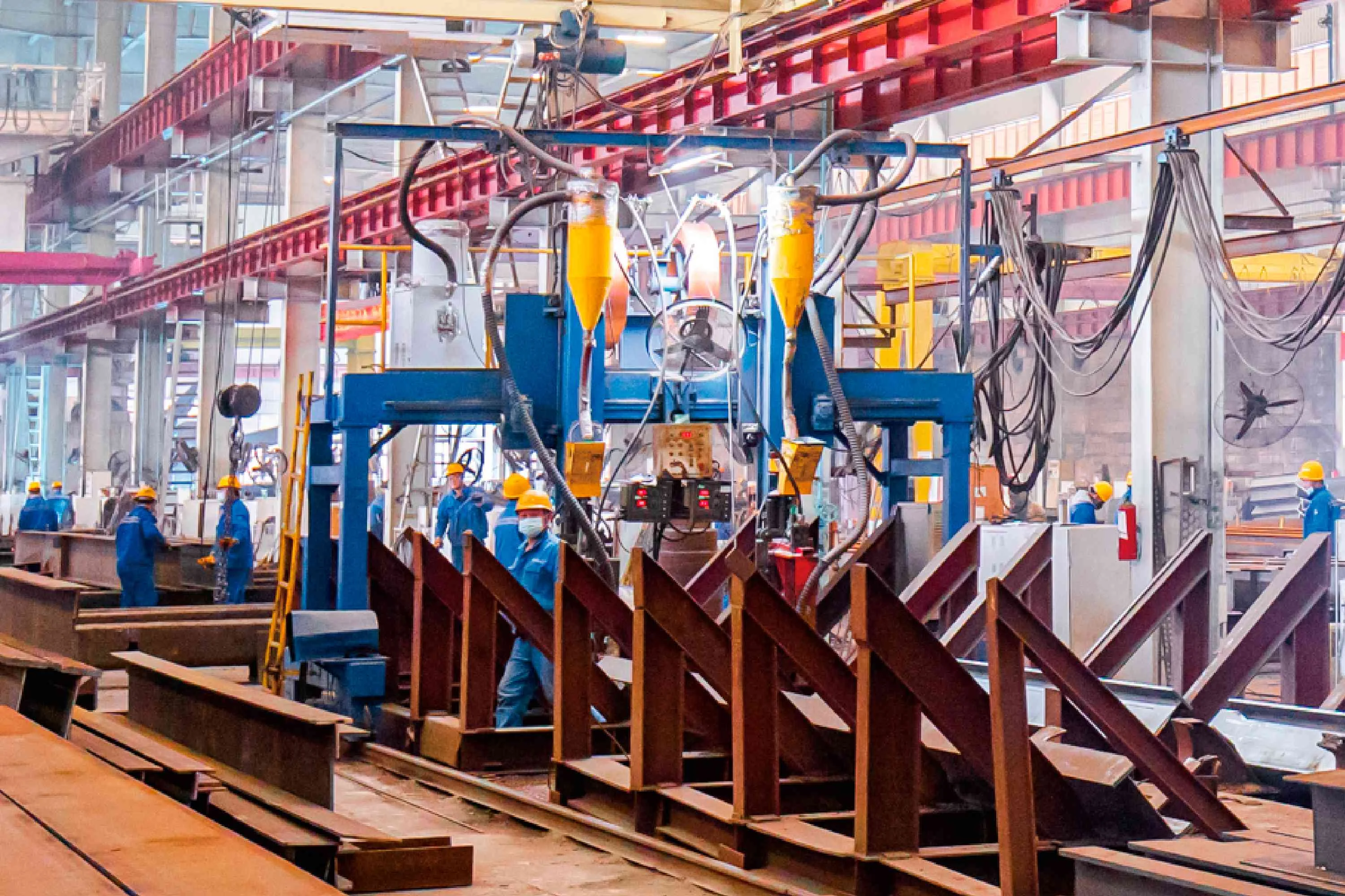
Shop Fabrication and Trial Assembly
Each truss module is fabricated in our Xuzhou facility: chord members cut to length on automated cutting lines, gusset plates CNC-cut to design geometry, web members fitted and welded using certified procedures. Every weld is inspected by visual, magnetic particle, and ultrasonic methods. The completed module is trial-assembled in the shop — bolted to its mating module on a flat assembly area to verify that the field connection geometry matches the design. Any discrepancy is corrected in the shop, where correction costs are minimal.
Transport and Route Survey
Module transport is planned in coordination with the route survey. For domestic projects, modules within standard permit limits (under 4m wide, under 25m long, under 30 tonnes) travel by standard flatbed. Oversized modules require special permits, escort vehicles, and route surveys that verify bridge load ratings, overhead clearance, and turning radius along the transport route. For overseas projects, modules are containerized or shipped as break-bulk cargo, with sea transport time factored into the project schedule.
Field Erection
On site, modules are positioned by crane and bolted to the previously erected module. For bridges over water, a launching sequence may be used: modules are assembled on one bank and pushed (launched) across the gap by hydraulic jacks, with a launching nose at the leading edge to cantilever across the span until it reaches the next pier. For bridges over land, modules may be lifted directly by crane onto the piers, or erected using a temporary falsework system.
Bearing Installation and Final Adjustment
Seismic isolation bearings are installed on the pier caps before the bridge module is lowered onto them. The bearings are positioned to their design elevation, and the bridge is adjusted to its final line and grade. The bearings are then grouted in place, locking the bridge geometry. For friction pendulum bearings, the sliding surface is protected with a temporary restraint that is removed after the bridge is complete and the bearing is ready to function in its seismic isolation mode.
Bridge Projects We Have Delivered
Hybrid
748 m Covered Bridge
A building-bridge hybrid structure combining pedestrian bridge engineering with enclosed envelope design. Modular truss system with shop-fabricated segments and bolted field connections. Thermal expansion designed for 60°C range.
Overseas
Pakistan Karot Bridge
Steel structure bridge project in Pakistan, with shop-fabricated segments transported internationally and erected on site. Seismic isolation bearing system for the regional seismic hazard.
Overseas
Pakistan Tarbela Bridge
Steel structure supply and fabrication for a bridge project at Tarbela, Pakistan. Fatigue design for traffic loads and shop-fabricated modular truss segments for international transport.
Planning a Steel Structure Bridge Project?
Send us your bridge type (highway, pedestrian, covered), span requirement, site seismic data, and traffic loading specification. Our engineering team will respond within 24 hours with a structural system recommendation, fabrication and transport plan, and budget quotation — backed by Class-1 contracting qualification and overseas bridge project experience.
Email: market@permanentsteelstructure.com | WhatsApp: +86 18621689980 | Phone: +86 516-83269982