
Column-Free Sightlines and Wind-Load Optimization for Stadium Roofs
Stadiums demand 80-120m clear spans for unobstructed spectator sightlines, cantilevered canopies that resist extreme wind uplift, and acoustic environments that amplify crowd energy without structural drumming. We engineer the grid, pipe truss, and beam-string systems that make it possible.
A Stadium Roof Is Not a Warehouse Roof with Bigger Spans
The fundamental difference between a stadium roof and a large industrial roof is not span magnitude — it is the combination of four engineering demands that no other building type encounters simultaneously.
First, sightline geometry. Every seat in a stadium must have an unobstructed view of the playing surface. This is not an aesthetic preference — it is a functional requirement that dictates structural column placement. Columns can only be located in "sightline shadow zones" — areas where a column's width does not obstruct any spectator's view of the field. In a typical oval stadium, these zones are narrow and irregularly distributed, forcing structural spans that are not uniform. A stadium roof grid is not a rectangular grid; it is a geometry tailored to the sightline analysis, with span lengths varying by location around the perimeter.
Second, wind dynamics on cantilevered canopies. Most modern stadium roofs are not fully enclosed domes. They are partial roofs — cantilevered canopies projecting inward from the perimeter, sheltering the seating bowl while leaving the field open to sky. A 30-40m cantilevered canopy is a wing-like surface exposed to wind from all directions. Wind does not simply push downward on this surface; it creates complex pressure distributions with strong suction on the upper surface, vortices shedding at the leading edge, and turbulent reattachment downstream. Without wind tunnel testing, these effects cannot be predicted accurately, and a canopy designed by code formulas alone may be dangerously under-designed for the actual wind environment.
Third, acoustic performance. A stadium roof is an acoustic reflector. A hard, flat metal roof reflects crowd noise back toward the field, amplifying the atmosphere that makes live sports compelling. But the same reflection can also amplify wind-induced drumming — the low-frequency throb generated by vortex shedding on the roof's leading edge. The structural design must balance acoustic reflectivity (which the architect wants) with vibration suppression (which the engineer requires). This is not solvable by adding acoustic panels after the fact; it must be addressed in the structural geometry itself.
Fourth, crowd-induced vibration. A stadium roof is not a static structure. When 50,000 spectators jump in unison during a goal celebration, they generate a dynamic load of 0.5-1.0 kN/m² at 2-3 Hz. If the roof's natural frequency is in this range, the structure amplifies the input — not just perceptibly, but visibly. A stadium roof that visibly bounces during crowd movements is a public relations disaster, regardless of whether it is structurally safe.
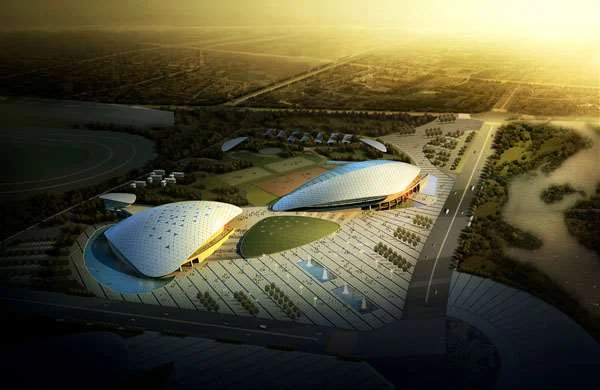
Structural Systems for Stadium Roofs
Why stadiums demand 80-120m spans, how grid topology affects sightlines, and when beam-string systems take over from pure grids.
Span Requirements and Sightline Optimization
A stadium seating bowl is typically 150-250m in diameter for a large venue. The roof must cover this diameter, or a significant portion of it, without interior columns. The span from the perimeter support to the leading edge of a cantilevered canopy is typically 30-40m for a partial roof. For a fully enclosed roof, the clear span across the full bowl diameter can reach 120-200m — a range where conventional double-layer grids become structurally inefficient and beam-string systems or cable-strut systems become the appropriate structural type.
The bolted sphere grid is the workhorse for stadium spans of 60-120m. For a 100m span, a double-layer or triple-layer grid with a depth of 6-8m achieves the span with a steel consumption of 25-40 kg/m². For spans exceeding 120m, the self-weight of a pure grid begins to dominate the structural demand — the grid is carrying its own weight more than the applied loads. At this point, a beam-string system becomes more efficient: the grid forms the upper chord, and prestressed cables replace the bottom chord, putting the grid into compression and the cables into pure tension. This hybrid system, which we deployed for our world-record 229m span coal shed, reduces steel consumption by approximately 30% compared to a conventional grid at the same span.
For cantilevered canopy sections, pipe truss structures provide the linear span and cantilever capacity. A pipe truss cantilever of 30-40m is achievable with a truss depth of 3-4m at the support, tapering to 1-1.5m at the leading edge. The taper is not merely aesthetic — it follows the bending moment diagram, placing material where forces demand it and removing it where they do not. The leading edge of the canopy is the critical wind design zone; vortex shedding at this edge generates the dynamic loads that govern the canopy's structural sizing.
Grid Topology and Spectator Sightlines
The arrangement of grid members — the topology — is not arbitrary. In a stadium, the grid must follow the sightline geometry. If the stadium is oval, the grid follows the oval curvature. If the seating bowl has varying rake angles (steeper in the upper deck, shallower in the lower), the roof's support column positions shift accordingly, and the grid span lengths vary around the perimeter.
A radial grid topology — members radiating from the field center and ring beams at regular intervals — naturally follows the circular geometry of many stadiums. Each radial truss spans from the perimeter to the leading edge, with ring beams tying the radial trusses together and distributing load circumferentially. The bolted sphere system accommodates this radial geometry because each node is independently drilled at the angles the geometry demands — no two nodes in a radial grid share the same bolt angle pattern.
For rectangular or ovoid stadiums, a rectangular grid with varying bay lengths may be more appropriate. The grid is laid out so that column positions coincide with sightline shadow zones, and span lengths vary to accommodate the non-uniform column spacing. The structural analysis must account for the varying spans — a uniform-section grid applied to varying spans results in some members being over-designed (wasting steel) and others under-designed (risking failure). Our optimization process assigns section sizes member-by-member, ensuring each member is sized for its actual force demand.
Wind Tunnel Testing for Cantilevered Roofs
For stadium canopies, code-based wind load calculations are insufficient. The complex geometry of a partial roof — open on one side, solid on the other, with a free leading edge exposed to flow — produces wind pressure distributions that no building code captures accurately. We require wind tunnel testing for all cantilevered stadium roof projects.
A wind tunnel model of the stadium and its surrounding terrain (including adjacent buildings that may channel or block wind) is constructed at 1:200 to 1:400 scale. The model is instrumented with hundreds of pressure taps on the roof surfaces. The tunnel generates wind at varying angles of attack and turbulence intensities, and the pressure taps record the instantaneous pressure at each location on the roof.
The data from wind tunnel testing reveals pressure distributions that are dramatically different from code assumptions. The leading edge of a cantilevered canopy experiences peak suction coefficients of -1.5 to -2.5 (compared to the -0.8 to -1.0 assumed by typical codes). The suction is not uniform — it peaks at the leading edge and decays rapidly within 5-10m. This means the canopy's leading-edge members must be designed for significantly higher uplift forces than the interior members. The structural design uses wind-tunnel-derived pressure coefficients for each grid zone, not a single uniform wind load applied to the entire roof.
Vortex shedding — the periodic shedding of vortices from the canopy's leading edge — generates a dynamic load at a frequency determined by the wind speed and the canopy's leading-edge geometry. If this frequency coincides with the canopy's natural frequency, resonance amplification occurs. The wind tunnel data identifies the critical vortex shedding frequency, and the structural design verifies that the canopy's natural frequency is sufficiently removed from it.
How a Stadium Roof Becomes an Acoustic Instrument
A stadium roof is a large acoustic reflector suspended 30-50m above the playing surface. When the crowd roars, the sound strikes the roof and reflects back toward the field and the spectators. A well-designed roof amplifies crowd noise by 3-6 dB — making the stadium louder and more intimidating for visiting teams, which is exactly what the venue operator wants.
The reflectivity of the roof depends on its material, geometry, and mass. A metal standing-seam roof with concrete deck overlay reflects mid- and high-frequency sound efficiently. A lightweight roof without mass transmits low-frequency sound rather than reflecting it, resulting in a thinner acoustic environment. The structural design must accommodate the mass of the acoustic deck without over-sizing the grid for weight that provides no structural benefit.
The challenge is that the same hard surface that reflects crowd noise also reflects wind-induced drumming. Vortex shedding at the canopy leading edge generates low-frequency pressure fluctuations (typically 0.5-2 Hz) that impinge on the roof surface. The roof structure transmits these fluctuations as audible low-frequency rumble — the "drumming" effect that stadium designers work to eliminate.
The structural solution is not to soften the roof surface (which would sacrifice crowd-noise amplification) but to stiffen the structure against the vortex shedding frequency. A stiffer canopy has a higher natural frequency, further from the vortex shedding band, reducing dynamic response. Stiffening is achieved by increasing the truss depth at the leading edge, adding diagonal brace members to stiffen the leading-edge frame, or installing tuned mass dampers at the points of maximum dynamic response. These are structural solutions to an acoustic problem — and they require coordination between the acoustic consultant and the structural engineer from the project's earliest stages.
Sports Venue Projects We Have Delivered
Sports
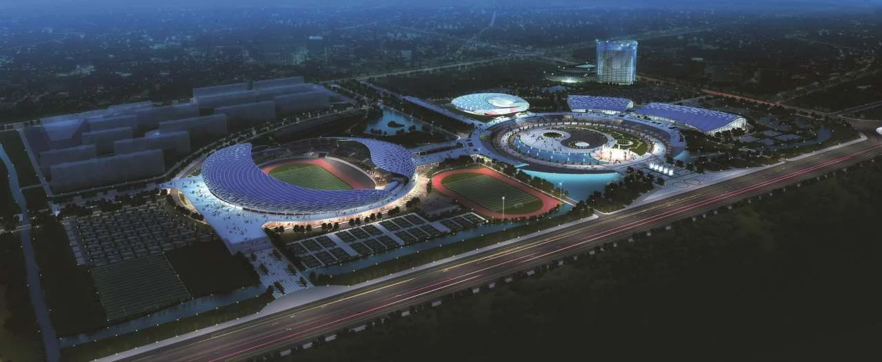
Modern Pentathlon Center
A multi-sport venue requiring column-free sightlines across the competition area. Long-span grid roof with cantilevered canopy sections, wind-tunnel-verified design, and crowd-induced vibration analysis for 20,000+ spectators.
 Cultural Sports
Jiaozuo Tai Chi Center
A cultural and sports venue combining traditional architectural elements with modern long-span steel structure engineering. Grid roof designed for acoustic performance and column-free sightlines across the main arena.
Structural Systems for Stadium Applications
 Primary
Bolted Sphere Grid
Double-layer and triple-layer grids for 60-120m stadium spans. Radial or rectangular topology tailored to sightline geometry. CNC-drilled nodes for non-orthogonal geometry.
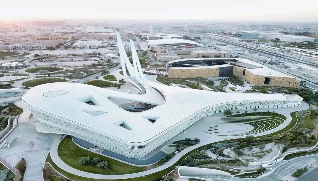 Cantilever
Steel Pipe Truss
Tapered cantilever trusses for 30-40m stadium canopies. Leading-edge stiffening against vortex shedding. Wind-tunnel-verified pressure coefficients for member sizing.
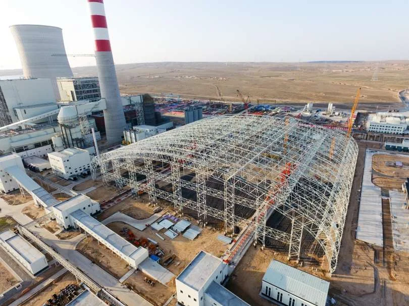 Ultra-Long Span
Beam-String System
Hybrid grid-plus-cable system for spans exceeding 120m. Reduces steel consumption by 30% versus pure grid. Cable pre-tensioning for controlled deflection. World-record 229m span.
Planning a Stadium or Arena Roof?
Send us your venue program, seating bowl geometry, sightline analysis, and climate data. Our engineering team will respond within 24 hours with a structural system recommendation, preliminary grid layout, and wind tunnel testing scope — backed by Special Grade qualification and experience on major sports venue projects.
Email: market@permanentsteelstructure.com | WhatsApp: +86 18621689980 | Phone: +86 516-83269982