
Steel Pipe Trusses — The Engineer's Long-Span Roof System
A steel pipe truss transfers roof loads through a triangulated network of circular hollow sections in pure axial tension and compression. It is the most material-efficient way to roof a station, an airport concourse, a stadium or an exhibition hall — and it is the system we hold a Special-Class manufacturing qualification for. Very few steel fabricators in China can say that.
What Is a Steel Pipe Truss?
A steel pipe truss is a triangulated framework built from steel tubes — typically circular hollow sections (CHS), or rectangular hollow sections (RHS) where architectural flat surfaces are required. The members are arranged in triangular units: two parallel chords (top and bottom) carry the bending action as an internal couple of tension and compression, while web members between them carry shear as diagonals. Because every joint is idealized as a pin, each member carries only axial force — there is nominally no bending in the members themselves. That is why a truss is so efficient: all of the steel is working, none of it is "idle" material resisting secondary moments.
The practical consequence is a structure that spans further, with less steel, than a solid beam of the same depth and weight. For a 60–120 m roof, members in pure axial action use roughly one-third to one-half the steel of an equivalent rolled-beam solution — which is why pipe trusses dominate large-span roof engineering worldwide.
A pipe truss differs from a spatial grid structure in its load path: a truss is a linear skeleton that spans in one principal direction, while a grid is a two-way lattice that distributes load in both plan directions. It differs from an H-beam truss in its members: the closed circular section has no weak axis, so its buckling resistance is the same in every direction — something an open I-section can never offer. We explain both comparisons in detail below.

Why Circular Hollow Sections Beat Open Sections
No Weak Axis
Buckling of a compression member is governed by its minimum radius of gyration — the direction in which it is weakest. An H-section has a strong major axis and a weak minor axis; the member's real slenderness is set by that weak axis, and the strong-axis material is partially wasted. A circular section has identical radii of gyration about every axis (ix = iy), so the material is fully effective in every direction. For the same cross-sectional area, a CHS typically provides a 20–35% higher minimum radius of gyration than an H-section, which translates directly into higher buckling resistance — or, put the other way, 20–35% less steel for the same axial load. In web diagonals and compression chords, this saving is realized on every member.
Torsional Rigidity of a Closed Section
A closed section's torsional constant J is orders of magnitude larger than an open section of similar area. Pipe trusses are frequently erected as long slender assemblies, lifted in segments, transported and braced temporarily — stages where open-section members can twist unpredictably. Closed tubes stay dimensionally stable, which simplifies handling, erection and camber control, and it also gives the finished structure real robustness against out-of-plane eccentricity at joints.
Aerodynamic Efficiency
The smooth cylindrical surface of a CHS has a drag coefficient roughly one-third of a flat plate (circular cylinder Cd ≈ 0.7 versus ≈ 2.0 for a flat face). For a long-span roof in an exposed location, wind is often the governing load — every reduction in Cd reduces the demand on chords, supports and foundations. The round surface also sheds rain and snow more readily and does not trap debris the way open section pockets do.
Less Surface, Less Coating, Less Fire Protection
For a given cross-section area, a circular section has the smallest surface perimeter of any section shape. Less surface means less blast-cleaning, less paint, less intumescent fire coating and less maintenance over the building's life — a running-cost advantage that owner-operators notice long after the architect has moved on.
An Honest Caveat
CHS joints are more complex to fabricate than bolted or welded H-section connections, and the closed section makes bolted site splices more difficult than open sections. That is why pipe truss manufacturing is a specialist trade — and why the qualification to do it at the highest grade matters. The economic optimum is not "always CHS", it is "CHS where axial efficiency and aesthetics dominate" — which is exactly the large-span roof application this page covers.
Tubular Joints: T, Y, X, K and KK — Gap vs Overlap
A pipe truss looks simple until you reach a node. At each node, three, four or five tubes converge at different plan and elevation angles onto a continuous chord. The joint is where the truss lives or dies — joints are classified by the geometry of the branch-to-chord intersection:
- T and Y joints — a single branch meeting the chord (perpendicular, or inclined); typical of mid-span web-chord intersections.
- X joints — two opposite branches; common at truss bottom-chord panel points where supports or hangers land.
- K and N joints — two branches on the same side of the chord forming a K or N pattern; these dominate prismatic trusses.
- KK (double-K) joints — two K joints on opposite faces of the chord, typical of three-dimensional truss systems.
K joints are further divided into gap joints and overlap joints. In a gap joint the branch toes are separated by a clear gap measured along the chord surface. In an overlap joint, one branch's wall overlaps the other, and the overlapped branch is welded to the through branch. Overlap joints carry load directly between branches and are stiffer, but they require multi-pass welding in constrained, partially hidden positions. Gap joints are easier to weld and inspect, so good design maximizes gap joints and uses overlap only where layout forces it. The governing parameters — the diameter ratio β = d1/D, the chord slenderness γ = D/2T, and the wall-thickness ratio τ = t1/T — decide the joint's failure mode: chord face plastification for small β, punching shear of the chord wall, sidewall yielding, or local buckling of the branch.
Because the branch meets a curved surface, the intersection is a three-dimensional saddle curve, not a flat miter. The weld around that curve has a continuously varying dihedral angle — the angle between the branch wall and the chord surface changes from the crown of the intersection to the toe. Dihedral angles below about 30° make weld accessibility and fusion quality genuinely difficult, and codes respond by requiring different weld details, throat sizes and inspection levels as the dihedral angle changes. This is exactly why the industry has moved to CNC pipe profiling, which cuts that saddle and its bevel programmatically rather than by hand.
For design, tubular joint capacity is checked to GB 50017 (Steel Structures Design Standard) with the CIDECT hollow-section joint design guides and EN 1993-1-8 as the international reference. Typical capacity checks cover chord face plastification, punching shear, chord wall shear and brace local buckling. For joints under fatigue loading — moving-crane buildings, or roofs with significant dynamic wind response — the weld detail and NDT class are upgraded to full-penetration welds with radiographic or ultrasonic verification.
Weld Geometry Reality
At the heel of a branch, the dihedral angle approaches 180° and the weld becomes a fillet; at the toe it approaches the acute range where full root penetration is practically impossible. Setting realistic weld details per zone of the intersection curve is what separates a manufacturable truss from a drawing-room fantasy.
Manufacturing a Pipe Truss: CNC Profiling, Welding and NDT
CNC Pipe Profiling
Branch pipes are cut on 5-axis CNC pipe cutting machines that generate the saddle intersection geometry and its continuously varying bevel in one program, from the 3D model. Cut plus bevel in a single pass eliminates the classic fabrication error — a saddle cut taken from a flat pattern and ground to fit, which leaves a variable root gap and invites weld defects. Our machines handle the standard 60–400 mm CHS member range, with bending of large tubes from 114–630 mm on hydraulic CNC benders.
Welding to Qualified Procedures
Every welding procedure is qualified to GB 50661 (welding of steel structures) and AWS D1.1, and every welder is certified for the specific joint type, position and thickness range they weld. Long chords are welded with submerged arc welding (SAW) for speed and consistency; branch-to-chord joints in all positions use gas-shielded flux-cored arc welding (FCAW) or manual arc welding for access. Preheat and interpass control follow the material grade and thickness — typically 100–150°C preheat above 30 mm wall.
NDT on Every Critical Joint
Full-penetration welds are verified by ultrasonic testing (UT); surface defects by magnetic particle (MT); and the most critical joints — typically peak-chord connections at supports — by radiographic testing (RT). NDT reports are lot-traced: each weld maps to its procedure record, welder, and inspection report, so a defect found in the field ten years from now can be traced back to its day of manufacture.
Digital Pre-Assembly
Complex nodes and complete truss segments are verified before shipment by 1:1 trial assembly where geometry is critical, plus 3D laser scanning compared against the BIM model for fabrication tolerance sign-off. For repetitive segments, a qualified trial assembly of first-off segments plus scanning of production segments provides the same assurance at a fraction of the yard time.
The Special-Class Pipe Truss Manufacturing Qualification
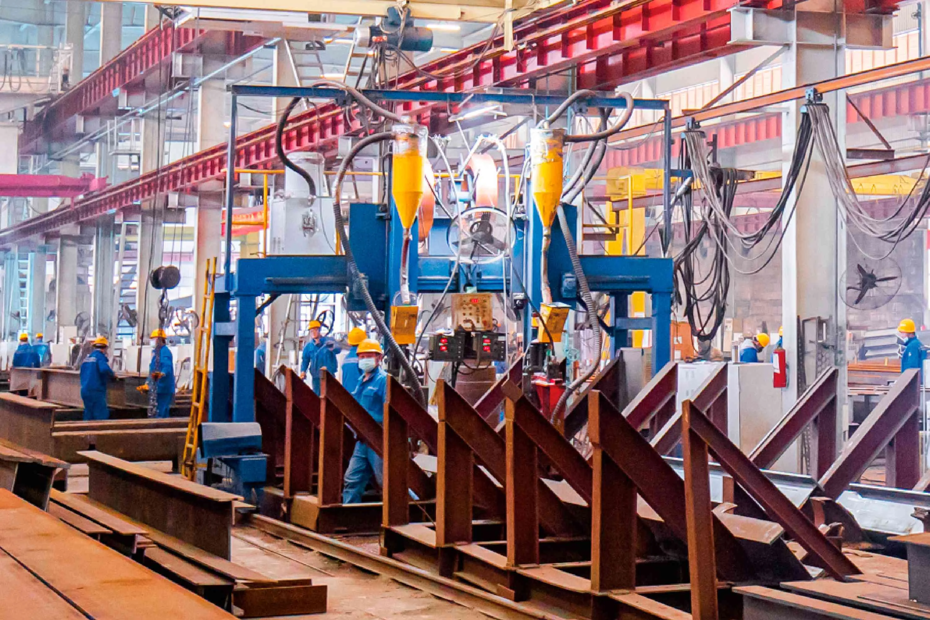
China grades steel structure manufacturing enterprises by a national rating system, and the Special-Class (teji) manufacturing qualification is the highest grade. It is held by very few companies in the country, and it is exactly the credential major infrastructure tenders — high-speed railway stations, airports, stadiums — require of their steel fabricators.
Holding Special-Class certification is not a wall plaque. It certifies that our quality management system, welding procedure coverage, NDT capability, skilled workforce and production capacity meet the standard required for the most demanding grid and truss structures in the country — and it is audited and re-verified. It is one of six top-level qualifications the company holds across bolted sphere grid, pipe truss and steel structure manufacturing.
For a project owner, this is what it means in practical terms: the trusses over your roof are being made by an organization that is already proven capable of the most complex structures in its class — under the same procedures, the same welders, and the same inspection regime.
Where Steel Pipe Trusses Are the Right Answer
| Application | Typical Span | Why a Pipe Truss |
|---|---|---|
| Railway & metro stations | 30–100 m | Curved canopy forms over platforms; long clear spans over tracks with zero mid-span columns; fast erection in restricted windows above live rail operations |
| Airport terminals & concourses | 40–120 m | Vaulted roofs of sculptural profile; large column-free check-in and boarding areas; good dynamic performance under crowd and wind loads |
| Stadiums & arenas | 60–120 m | Exposed structure as architecture; ring trusses and radial trusses carrying cantilever canopies around the bowl |
| Exhibition & conference centers | 40–120 m | Huge uninterrupted halls for booths and vehicles; adjustable roof clearances; service integration inside truss depth |
| Industrial long-span sheds | 60–150 m | Coal yards, stockpiles, maintenance hangars — maximum clear volume below, minimum steel above |
Daqing West Railway Station — 17,000 m² of Grid-and-Truss Roof at −35°C
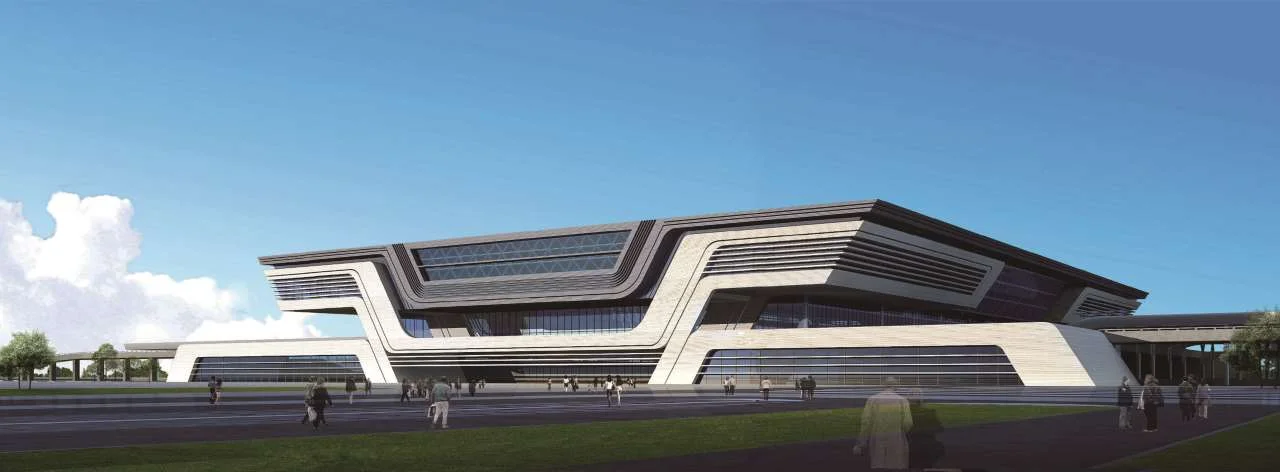
Daqing, in Heilongjiang Province, is one of China's great energy cities — home of the Daqing Oilfield — and Daqing West Railway Station is its gateway. The station roof is a 17,000 m² triangular pyramid grid combined with truss structures, with a 65-metre main span. The hybrid solution was not an accident: two-way grid spans the regular hall areas where its spatial action is most efficient, while linear pipe trusses carry the long clear spans and edge zones where a one-way structural line gives the architect the profile the station needed.
Daqing sits in China's severe cold climate zone (GB 50178), with a winter design temperature of −35°C and substantial snow load. Every weld detail, every steel grade selection and every erection sequence had to survive temperatures at which steel becomes brittle if the wrong grade, procedure or notch detail is chosen. And the construction window is brutally short — roughly six to seven months of working season a year in Heilongjiang.
The lesson of Daqing applies far beyond cold regions: full factory prefabrication plus fast site assembly is what makes long-span station construction achievable inside a short season. Every member arrived cut, welded, coated and numbered; site work was bolting, splicing and sealing. For owners, that is schedule certainty; for engineers, it is a proven reference that the same team can deliver complex, hybrid, weather-challenged structures — see more in our Daqing West Railway Station project and other infrastructure projects.
Steel Pipe Truss vs Spatial Grid Structure: How to Choose
Both systems are "space frames" in the broad sense, and both are in our manufacturing portfolio — we fabricate bolted sphere grids, welded sphere grids and pipe trusses under the same roof, so the selection advice below is not marketing for one product. The honest engineering rule is that the structure should follow the geometry of the space it roofs.
| Parameter | Steel Pipe Truss | Spatial Grid Structure |
|---|---|---|
| Load path | One-way — two chords plus web, spanning linearly | Two-way — orthotropic lattice distributing load in both plan directions |
| Best plan geometry | Linear halls, curved canopies, long strips, pitched roofs | Wide two-way spans over rectangles, squares, irregular column grids |
| Typical span range | 30–120 m (up to 150 m with heavy sections) | 40–150 m+ with two-way action |
| Depth / span ratio | 1/12 – 1/20 typical | 1/10 – 1/15 typical |
| Joint count | Few nodes — fewer welds, faster fabrication per ton | Many nodes — hundreds of hubs or welded joints |
| Architectural expression | Slim, flowing, sculptural — exposed structure as identity | Tectonic, uniform, cellular ceiling pattern |
| Site joints | Bolted chord splices at panel points | Bolted hub connections or welded patch nodes |
| When to choose | Curved or linear long spans; station canopies, concourses, stadium rings — see also curved box trusses and H-shaped trusses | Wide two-way roofs over regular plans — see our bolted sphere grid system |
Design Parameters: What We Work With
Span and Depth
Steel pipe trusses are economically viable from about 30 m and comfortable to 120 m with standard sections. Structural depth is typically 1/12 to 1/20 of the span — deeper for heavily loaded industrial roofs, shallower for architectural statements where the truss is exposed. Chord camber is specified to offset dead-load deflection and give the finished roof the intended profile.
Member Sizes
Standard member range is CHS 60–400 mm diameter, wall thickness 3.5–25 mm, in Q355B or Q345B steel. Chords are the larger-diameter continuous members; web branches are smaller. Large-diameter curved members (114–630 mm) are bent on hydraulic CNC benders for canopy and ring geometries. Where fire or corrosion dominates, member schedules can be upgraded with heavier coating specifications without changing the structure.
Loads and Codes
Design follows GB 50009 (loads), GB 50017 (steel design), GB 50661 (welding) and GB 50153 (reliability), with EN 1993-1-8 / CIDECT as the international joint-design reference. Snow, wind, seismic and temperature are all climate-specific — a 65 m station roof in Daqing governs on snow and −35°C material behaviour, while the same span in a coastal city governs on typhoon suction on the roof cladding system.
Practical Engineering Rules
- Long trusses need sliding supports or bearing shoes at one end to accommodate thermal movement — typically 40–60 mm of movement allowance per 100 m of steelwork.
- Roof deflection limit is commonly span/250 to span/400 depending on the cladding system; stiffer limits apply where ceiling movement would be visible.
- Vibration serviceability matters in public buildings: structure frequencies are checked against crowd and wind excitation, and walking comfort in floor zones above public spaces is verified.
- Fire protection of exposed chords uses intumescent coatings or board systems to the statutory rating; load-bearing redundancy is verified in the fire case so a single member failure cannot cascade.
Planning a Long-Span Roof or Station Canopy?
Send us your span, plan geometry, loading and architectural intent. Our engineering team — 50+ R&D engineers, with a joint research centre with Shanghai Jiao Tong University since 2023 — will come back with a pipe truss system recommendation, joint design approach, member sizing and a fabrication-oriented budget within 24 hours. We hold the Special-Class pipe truss manufacturing qualification and deliver design, fabrication and erection as a single responsible party.
Before you specify, review the welded connection options in depth: pipe truss connection design & fabrication specifications (K/T/Y/KT joints, EN 1993-1-8) →
Email: market@permanentsteelstructure.com | WhatsApp: +86 18621689980 | Phone: +86 516-83269982