
Curved-Roof Grid Structures for Column-Free Airport Concourses
Modern airport terminals demand 60-90m clear spans, architecturally curved roof forms, and structural integration with baggage handling, MEP, and daylighting systems — all under critical-infrastructure seismic performance objectives. We engineer, fabricate, and install the spatial grid and pipe truss systems behind them.
Why Airport Terminal Roofs Are Not Just Large — They Are Geometrically and Dynamically Complex
Most steel structure suppliers approach an airport terminal roof the same way they approach a warehouse: calculate the span, pick a truss depth, quote by the ton. This approach fails on airport terminals for three reasons that have nothing to do with span magnitude.
First, the geometry is curved. Airport terminal roofs are rarely flat rectangles. They feature barrel-vault curvature, wave forms, leading-edge sweeps, and skylight slots that follow the concourse axis. A flat double-layer grid can be adapted to curved forms, but only if the fabricator's CNC equipment can drill bolted sphere nodes at the precise non-orthogonal angles that the curved geometry demands — and only if the engineering team models the curved grid in 3D structural software, not in 2D bay-by-bay approximations.
Second, the dynamic environment is unlike any other building type. An airport concourse floor vibrates under the passage of thousands of passengers, electric baggage carts, and jet bridge connections. The roof structure above must not amplify these vibrations into perceptible oscillation. A long-span grid roof with an inappropriate natural frequency can couple with floor vibrations, creating a resonance that passengers feel as an unsettling ceiling sway — even though the structure is perfectly safe in strength terms. Serviceability, not strength, governs airport terminal roof design.
Third, the roof is a mechanical plant. A modern airport terminal roof supports HVAC ductwork of 1-2m diameter, baggage handling conveyor rails, fire suppression mains, approach lighting support, and passenger boarding bridge attachment points. Each of these systems penetrates the grid structure at specific nodes. The structural engineer is not designing a roof and then handing it to the MEP engineer to work around — the two disciplines must coordinate at the individual member level, because a grid member selected to carry a 2-tonne air handling unit changes the load distribution of the entire surrounding grid.
The Structural Logic of Airport Terminal Roofs
Why airports need 60-90m clear spans, and how grid geometry adapts to the curved architectural forms that define modern terminal identity.
An airport terminal concourse is, at its core, a circulation space. Passengers move through it from check-in to security to gate, often distances of several hundred meters. Retail and food service areas line the concourse walls. Boarding bridges project from the airside facade at intervals of 60-100m. For this program to function, the concourse interior must be column-free across its full width — typically 60 to 90 meters for a wide-body gate concourse.
Conventional steel framing — beams supported by columns at 18-24m intervals — is structurally possible at these spans but architecturally and functionally unacceptable. Interior columns would obstruct passenger flow, break up retail sightlines, and interfere with the baggage handling systems that run below the concourse floor. A spatial grid structure solves this by distributing the roof load through a three-dimensional network of steel members to the perimeter columns, achieving clear spans of 60-90m with a structural depth of only 5-7 meters (a depth-to-span ratio of approximately 1:12 to 1:15).
Grid Geometry for Curved Architectural Forms
The architectural vision for a modern airport terminal is rarely a flat box. Terminal roofs incorporate barrel-vault curvature for daylighting, wave forms for visual identity, and leading-edge cantilevers at the landside facade to shelter arriving passengers. A double-layer curved grid structure follows these forms while maintaining uniform structural depth across the span.
The bolted sphere grid system is particularly suited to curved geometry because each node is independently CNC-drilled at the precise angles the geometry demands. In a flat rectangular grid, all nodes share the same bolt angle pattern. In a curved grid, no two nodes are identical — each sphere is drilled to its unique position in the three-dimensional surface. Our CNC drilling equipment reads the node angle data directly from the 3D structural model, eliminating the manual angle calculation that introduces errors in less automated systems.
For larger terminal projects where the architectural form includes both curved and straight sections, we combine pipe truss structures with grid structures. Pipe trusses provide the linear span elements (straight concourse sections, cantilevered canopies), while curved grid sections handle the geometric transitions. The two systems share common support points and are coordinated in the structural model to ensure load transfer at the interface is correctly engineered.
Vibration Control for Passenger Comfort
A long-span roof structure has a natural frequency that depends on its span, depth, mass, and boundary conditions. For a 75m span grid roof with a 5m depth and typical cladding mass, the fundamental vertical natural frequency is typically 1.5-2.5 Hz. This range is problematic because it is close to the frequency of human walking (1.6-2.0 Hz) and the excitation frequency of electric baggage carts (2-3 Hz).
If the roof's natural frequency coincides with an excitation frequency, resonance occurs and the roof oscillates with perceptible amplitude. Passengers do not feel the roof strength — they feel the roof move. Even a 5mm oscillation at 2 Hz is perceptible and creates a sense of structural unease that undermines the terminal's architectural intent of stability and permanence.
We address this through three strategies, applied selectively based on the specific dynamic analysis of each project:
- Frequency tuning: The grid depth, member stiffness, and support conditions are adjusted in the structural model to shift the natural frequency away from the excitation band. Increasing depth from 5m to 6m on a 75m span may shift the fundamental frequency from 1.8 Hz to 2.4 Hz — enough to break resonance.
- Mass distribution control: Heavy elements (HVAC units, catwalks) are positioned at node points rather than mid-span, which changes the effective mass distribution and natural frequency without adding structural material.
- Damping augmentation: For particularly sensitive configurations, viscous dampers or tuned mass dampers are integrated into the grid at locations of maximum dynamic response. These devices absorb vibrational energy and reduce oscillation amplitude by 50-70%.
Baggage Handling System Integration Below
Modern airport terminals route baggage handling conveyor systems below the concourse floor, often suspended from the roof structure above rather than supported from the slab below. This means the grid roof that passengers see from above is also the structural frame that carries the baggage system from below. The bottom chord of the grid must accommodate:
- Conveyor rail supports: Steel angles welded to bottom-chord nodes at regular intervals, each carrying 500-2000 kg of conveyor and baggage load
- Maintenance catwalks: Grated walkways suspended from the grid for baggage system access, adding dead load and requiring guardrail attachments
- Electrical and data conduits: Cable trays routing power and control signals to the baggage system motors
- Fire suppression piping: Dry-pipe sprinkler mains sized for the baggage system area, which can be 100-150mm diameter steel pipe
Each suspended element adds dead load to specific grid members. The structural analysis must include these point loads at their actual positions — not distributed as uniform area load, which is the simplification that many fabricators use. A point load of 2 tonnes on a bottom-chord member changes the force in that member, in the adjacent members, and in the node connections. If the analysis does not capture this, the member may be undersized and the connection may fail under fatigue loading (baggage conveyors vibrate continuously, creating millions of load cycles over the terminal's design life).
Four Problems Unique to Airport Terminal Steel Structures
Wind Uplift on Large Roof Areas
A 90m span roof presents enormous windward and suction area. Wind tunnel testing typically reveals that the critical load case is not downward gravity but upward wind suction — the force attempting to peel the roof from its supports. Under suction, compression members become tension members and vice versa. Every bolted connection must be designed for bidirectional force, which is inherent to the bolted sphere system but must be explicitly verified in the analysis. Sliding support connections at the perimeter allow controlled thermal movement while resisting wind uplift through hold-down anchors sized for the full suction force.
Acoustic Performance Under Flight Paths
Airport terminals are, by definition, under flight paths. The roof structure must attenuate exterior aircraft noise while supporting the acoustic ceiling system below. A steel grid roof with standing seam metal cladding provides approximately 35-40 dB of airborne sound insulation. For terminals under departure corridors where noise levels exceed 85 dB, the roof buildup includes a secondary acoustic layer: mineral wool insulation batts between the grid layers, a resilient channel system suspending the ceiling, and acoustic sealant at all penetrations. The grid depth that provides structural span also creates a plenum for acoustic treatment — another reason why depth-to-span ratio matters beyond pure strength.
Daylighting Integration Without Thermal Penalty
Modern terminal design emphasizes natural daylighting to reduce energy consumption and improve passenger experience. Skylight bands and glazed seams are integrated into the grid roof at intervals along the concourse axis. Each skylight opening creates a discontinuity in the grid — members that would have run through the opening must be redirected around its perimeter, creating concentrated load paths at the opening edges. The structural engineering must account for these openings without simply over-sizing all adjacent members, which would add weight and cost. Instead, the grid topology is locally modified: additional diagonal members frame the opening, transferring load to adjacent bays while maintaining the architectural daylighting intent.
Seismic Performance as Critical Infrastructure
Airport terminals are classified as critical lifeline facilities. Under the Chinese seismic design code (GB 50011), they must remain functional after a design-level earthquake — not merely survive without collapse. This "operational" performance objective means primary structural members must remain essentially elastic under the maximum considered earthquake. Long-span roofs respond to vertical seismic input dramatically more than conventional floor structures because their vertical natural period (1-3 seconds) is closer to the dominant frequencies of vertical ground motion. The grid's vertical seismic capacity must be explicitly checked, and the roof-to-column connections must accommodate relative displacement through slotted bolt holes and yielding fuse elements that dissipate seismic energy without transferring damaging forces to either the roof or the supporting structure.
How We Engineer Airport Terminal Roofs — From Model to Installation
Integrated 3D Structural Modeling
Every airport terminal roof we engineer begins as a complete 3D structural model. The architectural surface — whether flat, curved, or freeform — is imported into our structural analysis software. Grid topology is generated on the architectural surface, with member sizes initially assigned by engineering judgment and then optimized through iterative analysis. Load cases include dead load (steel self-weight, cladding, MEP, ceiling, baggage system), live load (maintenance access, snow), wind (pressure coefficients from wind tunnel testing or CFD), seismic (response spectrum analysis with vertical component), and temperature differential (for exposed or semi-exposed structures).
Member forces are extracted for every member in every load combination. The governing force — compression, tension, or reversal — determines the member section size. Connection forces at each bolted sphere node determine the bolt diameter, sphere hole angles, and sealing plate specifications. This is not a spreadsheet calculation applied uniformly across the grid; it is a member-by-member, node-by-node analysis that produces a fabrication package where no two spheres in a curved grid are identical.
CNC Fabrication and Trial Assembly
40Cr forged steel spheres are CNC-drilled at the angles defined by the 3D model. Q355B steel tubes are cut to design length on automated cutting lines, with conical sealing plates welded to tube ends using certified welding procedures and non-destructive testing verification. The entire grid is trial-assembled in our factory in sections to verify geometric compatibility before shipment — a quality control practice that catches fabrication errors in the factory rather than on the construction site, where correction costs are 10-50 times higher.
For airport terminals, trial assembly is particularly critical because of the curved geometry. A flat grid can be assembled on a flat factory floor and measured against a 2D drawing. A curved grid must be assembled on a curved jigs that replicate the roof's final geometry, with 3D surveying verifying that each node position matches the model within tolerance. Any deviation is corrected before shipment — not after the crane has lifted the section 20 meters into the air.
Erection Sequencing and Deflection Monitoring
A long-span grid roof cannot be lifted into place as a single unit. It is assembled section by section on temporary shoring towers, with each section checked against the 3D model before the next is installed. The partially completed structure must support itself and resist construction-period wind loads before the grid achieves self-supporting geometry through closure of the final connections.
During erection, deflection is monitored at critical points using survey instruments. Predicted deflection under self-weight is compared to actual measured deflection as each section is installed. Deviation exceeding 15% of predicted triggers an engineering review. Pre-camber — a slight upward curvature built into the fabrication — compensates for dead-load deflection so the roof settles to its design position under permanent load rather than sagging below it.
Airport Projects We Have Delivered
China
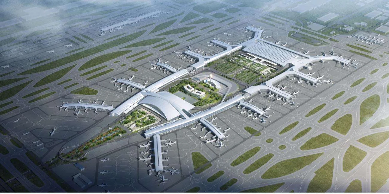
Guangzhou Baiyun Airport T3
Phase III expansion with 80m+ column-free concourse span. Spatial grid roof engineered for seismic critical-infrastructure performance and integrated MEP/baggage systems.
 Overseas
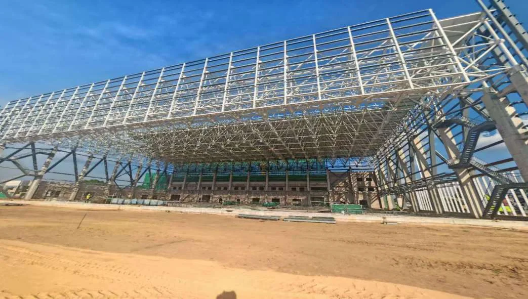
Congo Airport Project
Steel structure supply for an international airport in Central Africa, designed for tropical climate corrosion resistance and large-span terminal roof performance.
 China
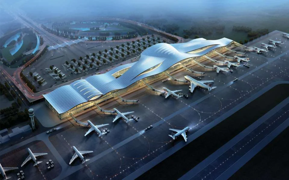
Xuzhou Guanyin Airport
Regional airport terminal with curved grid roof structure, integrating natural daylighting bands and seismic isolation connections at the column-roof interface.
Structural Systems for Airport Terminal Applications
 Primary System
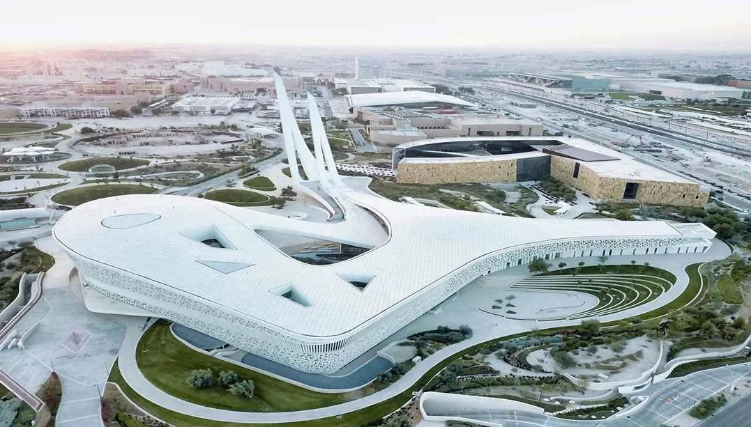
Bolted Sphere Grid Structure
Factory-prefabricated nodes with CNC-drilled angles for curved geometry. Bolted field assembly with torque verification. Bidirectional force capacity for wind uplift. The primary structural system for airport terminal roofs requiring 60-90m clear spans.
 Secondary System
Steel Pipe Truss Structure
Linear span elements for terminal canopies, boarding bridge support frames, and straight concourse sections. Combines with curved grid sections for terminals with mixed geometric forms. Welded or bolted connections based on span and load requirements.
Planning an Airport Terminal Project?
Send us your terminal program, architectural concept, loading requirements, or even a span target. Our engineering team will respond within 24 hours with a feasibility assessment, preliminary grid layout, and budget quotation — backed by Special Grade manufacturing qualification and a proven track record on international airport projects.
Email: market@permanentsteelstructure.com | WhatsApp: +86 18621689980 | Phone: +86 516-83269982