
Heavy Crane Integration and Fatigue Design for Industrial Workshops
A 50-tonne overhead crane does not just add load to a building — it transforms the structure into a dynamically loaded machine. Column sizing, fatigue-rated runway beams, vibration control for precision manufacturing, and fire protection systems must all be engineered as one integrated system, not assembled from disconnected components.
Why an Industrial Workshop with a 50t Crane Is Not a Bigger Warehouse
Most steel structure suppliers quote industrial workshops by the square meter: span × length × height × unit price. The overhead crane is treated as a line item — "add X yuan for a 20t crane runway." This approach ignores the fundamental reality that a heavy crane transforms the structural design from static to dynamic, from strength-governed to fatigue-governed, and from a simple span calculation to a complex interaction between moving loads, lateral braking forces, and structural natural frequencies.
The 50-tonne overhead crane is the inflection point. Below 10-15t, crane loads are a minor addition to the gravity load — the structure barely notices. Above 50t, the crane dominates the structural design. The columns must be sized not for the building's dead load but for the crane's maximum wheel load applied at the worst position. The runway beam must be designed for fatigue — millions of load cycles as the crane traverses the bay. The building frame must resist lateral braking forces from the crane's acceleration and deceleration. And the entire structure must be checked for vibration compatibility with the manufacturing processes happening below.
We hold the Class-1 Steel Structure Specialized Contracting qualification and the Special-Class steel structure manufacturing qualification — the highest tiers in China's system. For industrial workshops, this means we are authorized to design and manufacture structures for any crane capacity, any span, and any industrial classification. Our 200,000-ton annual capacity and full-industry-chain setup — from steel component fabrication through insulated panel manufacturing through on-site installation — means the crane runway, the structural frame, the wall cladding, and the roof system are all engineered by one team, to one set of tolerances, with one point of accountability.
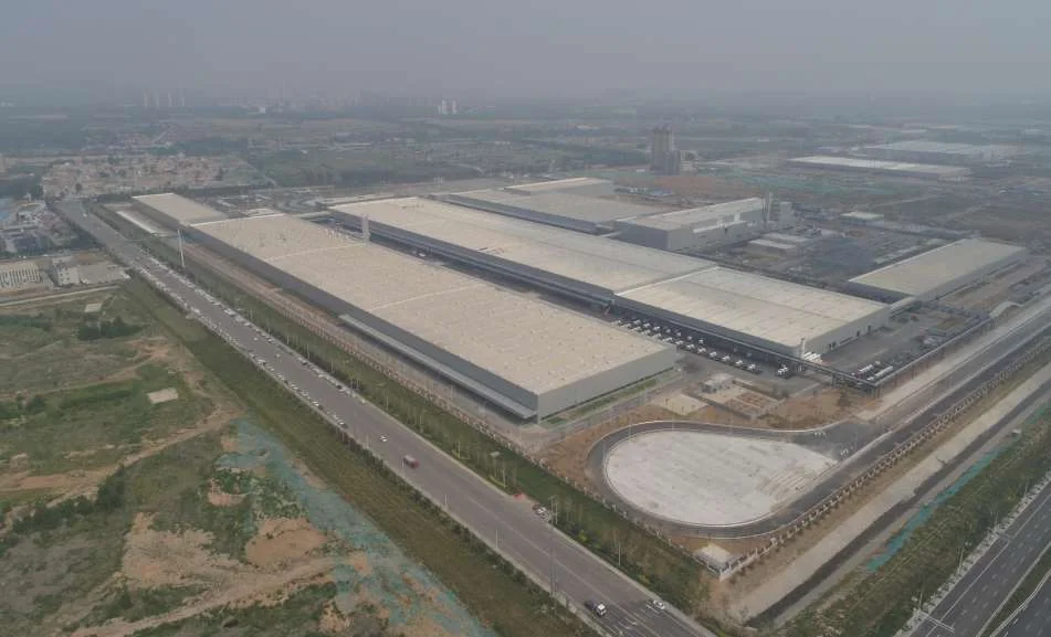
How a 50t Crane Dictates the Structural Design
Column sizing, fatigue analysis, vibration control, and fire protection — the four engineering systems that heavy crane integration demands.
Column Sizing: The Crane Is the Governing Load
In a typical industrial workshop without cranes, columns are sized for gravity load (roof dead + live + snow, wall cladding weight) and lateral load (wind, seismic). For a 24m span, 8m eave height workshop, a gravity column might be an H-section of 400×200×8×12 — approximately 60 kg/m. Add a 50t overhead crane, and the column must now resist:
- Vertical crane wheel load: A 50t crane with its trolley at maximum offset transfers up to 350-400 kN per wheel pair to the runway beam, which transfers it to the column. This is on top of the gravity load.
- Lateral braking force: When the crane brakes while traversing, it generates a horizontal force of approximately 10-20% of the lifted load — 50-100 kN for a 50t crane — applied at the runway beam level, 6-8m above the column base.
- Longitudinal braking force: When the crane brakes along the runway direction, it generates a longitudinal force that must be transferred through the runway beam to the building's lateral bracing system.
- Cranes-sway impact: The dynamic amplification factor for crane loads is typically 1.25-1.40, accounting for the impact of lifting loads from rest and the acceleration/deceleration of the trolley.
The column that was 400×200×8×12 without a crane becomes 500×500×20×25 or larger — roughly 250 kg/m — with a 50t crane. The column base connection, anchor bolts, and foundation must be re-sized for the combined vertical, lateral, and moment loads. This is not a "bigger column" — it is a fundamentally different structural design that begins with the crane's load characteristics, not the building's geometry.
Fatigue Analysis for Crane Runway Beams
A crane runway beam is one of the few structural elements in a building that is explicitly designed for fatigue. Unlike gravity beams, which are loaded statically and continuously, a runway beam experiences a moving point load that cycles millions of times over the building's design life. A workshop operating two shifts per day, 250 days per year, with 50 crane lifts per shift, accumulates 2.5 million load cycles in 10 years. Over a 30-year design life, that is 7.5 million cycles.
Fatigue design is governed by the stress range — the difference between maximum and minimum stress at a given point in the beam during one load cycle — and the number of cycles. The critical details are not the beam itself but the connections: the welds connecting the rail-clip plates to the top flange, the welds connecting the web stiffeners, and the end-plate connections to the column. These are the fatigue-critical details where cracks initiate and propagate.
Our runway beam design follows GB 50017 (Chinese steel structure design code) and AISC 360 (where required for international projects), with the following fatigue-specific provisions:
- Rail-clip plate connection: Fillet welds sized for the fatigue category, with grinding of weld toes to reduce stress concentration. For heavy-duty cranes (Class A6-A8 per FEM 1.001), bolted clip plates replace welded clips to eliminate fatigue-prone weld details entirely.
- Web stiffener connection: Stiffeners are fitted (bear against the top flange) to transfer wheel load directly, without relying on weld shear. This reduces the stress range in the stiffener-to-web weld.
- End-plate connection: The runway beam's end connection to the column is designed as a pinned connection, not a moment connection. This prevents the beam from attracting end moments under differential settlement or frame sway, reducing the stress range at the connection.
- Camber and rail alignment: The runway beam is cambered to compensate for dead-load deflection, and the rail is installed to a straightness tolerance of L/1000. A misaligned rail introduces lateral wheel forces that accelerate fatigue damage and wheel wear.
Vibration Control for Precision Manufacturing
Modern industrial workshops house manufacturing equipment that is increasingly vibration-sensitive. CNC machining centers, coordinate measuring machines, precision presses, and semiconductor fabrication equipment all have floor vibration limits measured in micrometers — often below 5 μm for frequencies of 1-50 Hz. A 50t overhead crane operating overhead, or a press stamping 800 times per minute, can generate floor vibrations that exceed these limits by an order of magnitude.
The steel structure is not the vibration source — the equipment and the crane are. But the steel structure's stiffness, mass distribution, and damping characteristics determine whether vibration from the source is amplified or attenuated at the sensitive equipment location. A steel frame with a natural frequency that coincides with the equipment operating frequency will amplify vibration. A frame with a natural frequency well separated from the equipment frequency will not.
We address vibration control through:
- Frequency separation: The frame's natural frequencies are calculated and compared against the operating frequencies of the specified equipment. Where coincidence is detected, the frame stiffness is adjusted (through deeper beams, stiffer columns, or additional bracing) to shift the natural frequency away from the excitation band.
- Equipment isolation pads: Vibration isolation pads under equipment bases decouple the equipment from the floor structure, reducing transmitted vibration by 80-95% above the pad's resonant frequency.
- Crane isolation: The crane runway beam is isolated from the column with elastomeric bearing pads that reduce crane-induced vibration transmission to the building frame.
- Strategic column placement: Vibration-sensitive equipment is located as far as possible from crane runways and heavy press foundations, with the distance calculated to achieve the required attenuation.
Insulated Envelope and Fire Protection Systems for Industrial Facilities
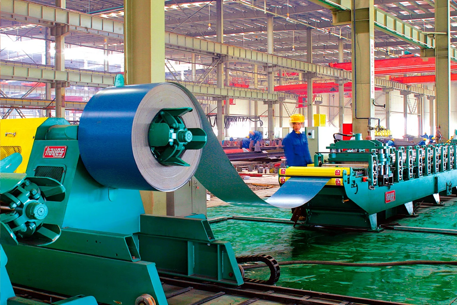
Insulated Panel Envelope
An industrial workshop's envelope — walls and roof — is not just weatherproofing. It is a thermal, acoustic, and fire-rated system that must perform for decades in an industrial environment. We manufacture the sandwich panels and wall cladding panels that form this envelope, integrating them with the structural frame at the design stage rather than bolting them on as an afterthought.
For workshops with temperature-controlled processes (food processing, pharmaceutical, electronics), the envelope insulation value is dictated by the process requirement, not the climate. A cold-room workshop for food processing may require 150-200mm of PIR insulation (R-value of 8-11 m²·K/W) in the walls and roof. The panel thickness affects the structural connection design: a 200mm panel requires a different eave trim, gable trim, and flashing than a 50mm panel, and these details must be coordinated between the structural and envelope design teams.
Fire Protection Systems
Industrial workshops with heavy manufacturing processes are subject to fire protection requirements that vary by building classification, occupancy, and process hazard. Steel structure fire protection is not optional — bare steel loses 50% of its yield strength at 550°C, a temperature achievable in a flash fire within 5-10 minutes. For a column carrying 400 kN of crane load, a 50% strength reduction is catastrophic.
Fire protection methods we engineer into the structural design include:
- Intumescent paint: Applied to the steel surface, expands under heat to form an insulating char layer. Typical fire resistance ratings: 60-120 minutes. Preferred for exposed architectural steel where appearance matters.
- Board enclosure: Fire-rated boards (calcium silicate or vermiculite) screwed to the steel section. Typical ratings: 60-180 minutes. Preferred for columns and runway beams where durability is more important than appearance.
- Spray-applied fireproofing: Cementitious or mineral fiber spray applied to the steel surface. Typical ratings: 60-240 minutes. Preferred for large surface areas (roof structure) where cost efficiency matters.
The fire protection thickness is calculated based on the section factor (Hp/A ratio) of each steel member — the ratio of heated perimeter to cross-sectional area. A slender member (high Hp/A) requires more fire protection than a stocky member (low Hp/A). The calculation is member-specific, not a uniform thickness applied to all steelwork.
Seismic Performance of Industrial Structures with Heavy Cranes
An industrial workshop with a 50t overhead crane presents a unique seismic design challenge: the crane itself is a large mass suspended from the roof structure. During an earthquake, this mass acts as a pendulum — swinging laterally with respect to the building frame, generating horizontal forces at the runway beam level that are not captured by conventional seismic analysis.
The crane's seismic contribution depends on its position in the bay at the time of the earthquake. A crane parked at the center of the bay generates different lateral forces than one parked at an end bay. The most conservative analysis assumes the crane at the position that generates maximum force — typically at the bay end, where the lateral force from the swinging crane mass combines with the seismic force on the building frame at that location.
Our seismic design for industrial workshops follows GB 50011 for projects in China and the relevant international code (IBC/ASCE 7, Eurocode 8) for export projects. The crane mass is included in the seismic mass of the structure, and the crane's lateral force is calculated using the equivalent lateral force procedure or modal analysis, depending on the structure's period and irregularity classification.
For workshops in high-seismic zones (seismic intensity 8+ on the Chinese scale, or seismic design category D+ in ASCE 7), we design the crane runway support brackets as yielding fuse elements. These brackets are detailed to yield in a controlled manner at a predetermined force level, absorbing seismic energy and protecting both the crane runway and the primary structural frame. After a design earthquake, the brackets are inspected and replaced if necessary — a much simpler and cheaper repair than replacing a cracked column or a failed connection.
Additionally, the industrial building system must accommodate the relative displacement between the roof structure and the wall panels during seismic events. The wall panels are connected to the structural frame with slotted connections that allow controlled movement, preventing the panels from cracking or dislodging under inter-story drift.
Industrial Workshop Projects We Have Delivered
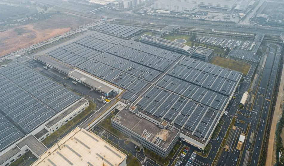 Automotive
GAC New Energy Workshop
Automotive manufacturing facility with heavy-duty overhead cranes, vibration-controlled foundation for precision robotics, and insulated envelope for climate-controlled assembly environment. Full structural and envelope system integration.
Heavy Truck
Sinotruk Workshop
Heavy truck manufacturing facility with 50t overhead cranes, fatigue-rated runway beams, and seismic design for industrial classification. Fire protection systems integrated with structural framing.
Planning an Industrial Workshop with Heavy Cranes?
Send us your crane specifications (capacity, span, duty class), workshop program, process requirements, and site seismic data. Our engineering team will respond within 24 hours with a structural system recommendation, column and runway beam sizing, and budget quotation — backed by Class-1 and Special-Class qualifications.
Email: market@permanentsteelstructure.com | WhatsApp: +86 18621689980 | Phone: +86 516-83269982